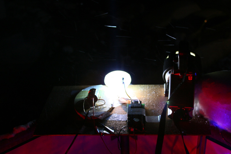
Cyclops Thor 15MCP to 120 Watt UHP

danjoo

Newly Enlightened
Joined
Sep 15, 2009
Messages
34
Location
Bielefeld Germany
Hi Guys,

Iam not sure where to post this, here or in the "Homemade and Modified" section.
@Mods
if its wrong here, please move it, thanx

Inspired by the Nightsword tread, i want to build a light with an UHP Lamp.
http://www.candlepowerforums.com/vb/showthread.php?t=239998


This are the Components i have bought so far:
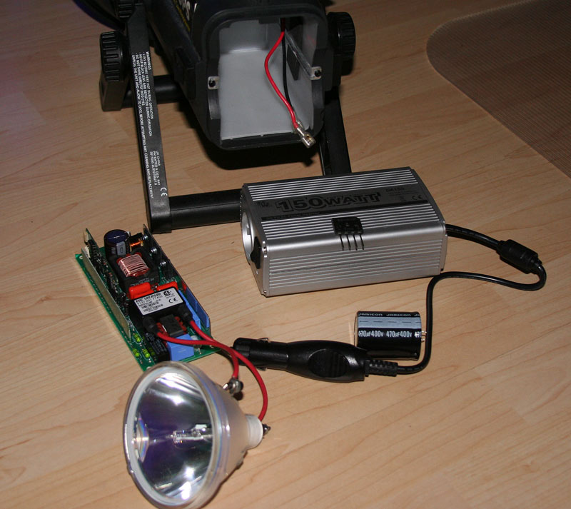
allcomps.jpg


-Thor Cyclops 15MCP ;)
-UHP lamp in reflector rated 100 watt ( TOP F5 UHP 100W 1.3 101464069 )
-UHP lamp driver for 120 watt ( EUC 120 P/L00 9137 001 77405 ), fit not exactly with the lamp i think, but i expectd that it is good to start and drive the lamp.
-Elko Capacitator 470 µF/400V
-Bridge Rectifier GBU808 560V
-Power Converter 150Watt for Car use.

My resarch til now say that my UHP driver need something between 220 and 400 Volt DC.

I dont find the exact datasheet for this driver but a list for some similar drivers to get a idea about the input Voltage. Here:
http://directories.csa-international.org


If i connect everything i can hear some cheep sound and i think the driver is ready to start.

But it does not start.

Please help my out. :mecry:

Mayby the driver need switch signal by the Origin Projector.
There is a connect terminal but i have absolutly no clue what kind of switching is there required.
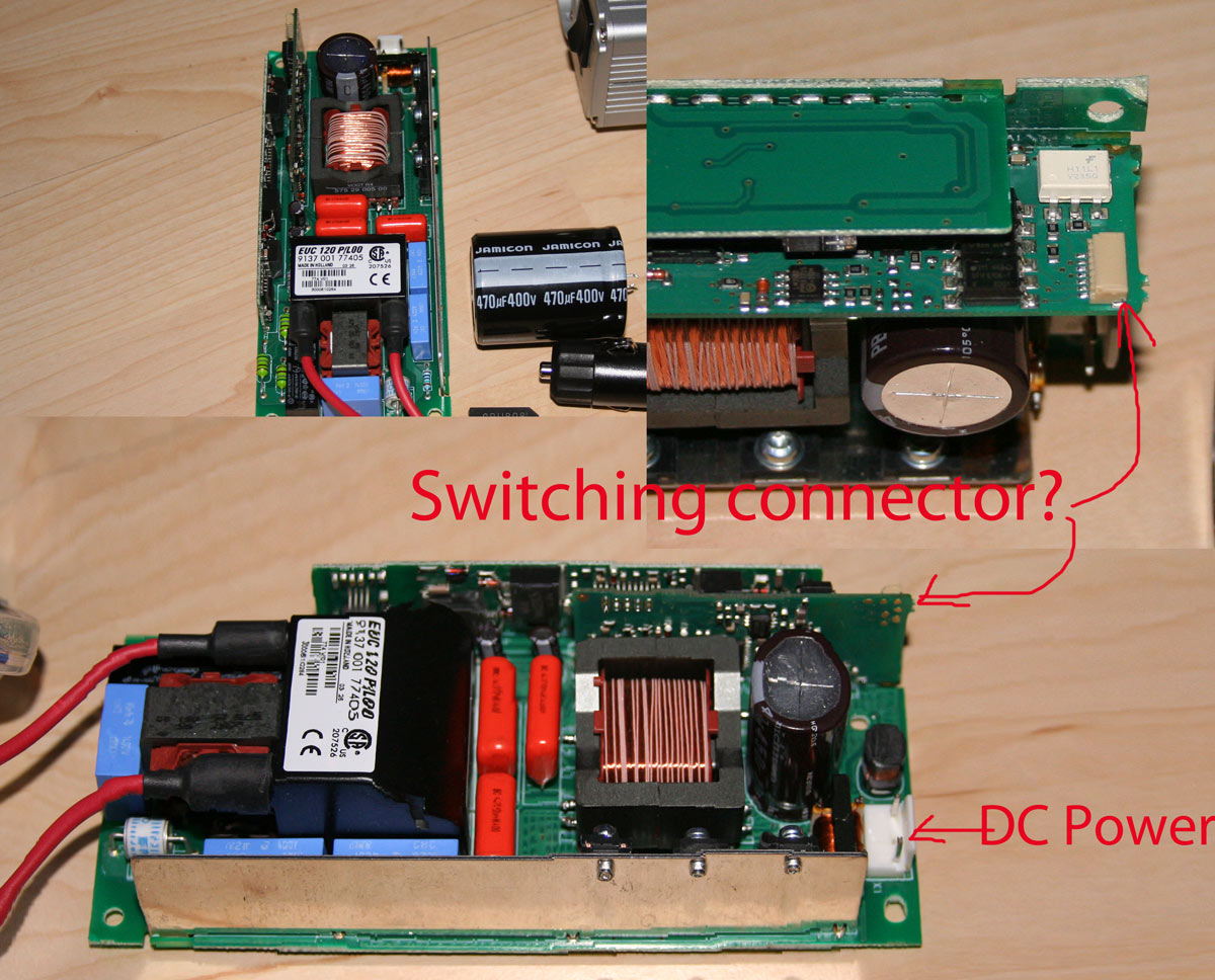
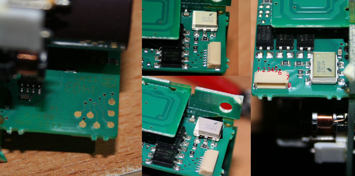
connector.jpg


I think about shorting one after the other connecter to switsch something.
Is this a good idea?
Or will this kill the driver? is maybe a signal needed instead of a shorting?

Any Idea is appreciated.

Thanx and Merry Cristmas


Daniel
 
Last edited:
Re: UHP Lamp Driver, help needed please

That inverter does not provide sinus output, but square or quasi-square wave so when you rectify it, you will not have 325 V DC but rather 230 V DC. If your ballast runs on 220-240 V AC, it is about 100 V short of starting. I'm not an expert on UHP Hg but that ballast looks like a Philips one, considering the land of origin and font for the text on it...

You should not need the rectifier bridge and capacitor in the first place if the inverter is doing its job and the ballast is rated for that low DC voltage.

If the ballast however should run on 160 V AC (220 V peak), then this is not the problem. Measuring the waveforms and voltages on the ballast would be helpful but deadly if you don't know what you are doing or do but slip or fail.
 
Last edited:
Re: UHP Lamp Driver, help needed please

Reading http://support.gateway.com/s/Manuals/HomeTheater/56in_RPTV_Service_Manual.pdf, as I understand it, the PFC front-end converter provides 380 V DC to the ballast which would explain why the TV is multi-range as well (90-260 V AC). This does not say that your statement that the ballast would run down to 220 V DC isn't true, but if Philips does require their costumers to use PFC, this would explain why your 230 V DC wouldn't start the ballast.

Still haven't found Philips datasheet for the ballast though...

EDIT: Found this. link It didn't list the EUC 120 P/L00 but other variants of 120 P being 280-400 Vdc or 220-410 Vdc so you are either just at or 50 V short of it.
 
Last edited:
Re: UHP Lamp Driver, help needed please

@winni

many thank for your anwers.

Yes it is from Philips on other places is a philips print.

I forget to say i have had this ballast already connected with a labor supply up to 400 Volt clean DC.
My local Electronic strore like to help my and connect it to a excellent power supply wich is able to supply 400V DC.
The beep sound from the ballast is the same like on 220 V DC.

In this link the second driver starts with 220Volt DC.

I think, this is not the point!

I think i have figured out that the ballast must be switchd on, maybe there:


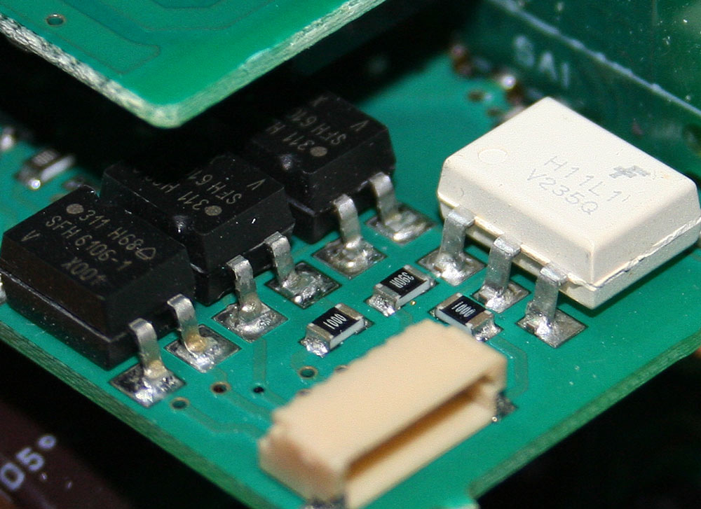
closeup.jpg


I work with the curves in photoshop to show the inscription an the white box thingy.
This is a optical switsch, pdf datasheet here.

I write some red Numbers to the pin from the connecter.

Maybe its a good idea to give some volt to pin 6 and 7, to switch the switch that the supply starts. :confused:
I think about 4,5 volt on pin 6 and 7.


Sorry that i dont write bevor that i had it already tested at 400VDC.


Any Ideas how to switch this beast?

Daniel
 
Last edited:
Re: UHP Lamp Driver, help needed please

Sorry about the delay, had some Christmas and New Year to celibate, the later with electric fireworks ignition...


I can see four optocouplers, three SFH610 and one H11L1. The one closest to pin 1 and 2 are for communication FROM the ballast to the TV/monster-HID-flashlight (depending on sexual preferences and current diagnose or general level of sanity). The three other is for communication to the ballast.

The three resistors are probably for interfacing against some logic level from the TV in order to limit the current though the optocouplers. Can you read out the values on them? The pictures does not have enough resolution for me to read the values.

Once you have the resistor value, you can calculate what the logic level is according to U1 = 0,01*R + 1,2 for the H11L1 and U2 = 0,02*R + 1,25 for the SFH610-1. It's probably 3,3 or 5 V for both, or should be with some rounding off.

Then it's only a matter of applying that between 3-4 and/or 5-6 and/or 7-8. 3, 5 and 7 is plus, 4, 6, 8 is minus. There are eight combinations you might have to try.

Good luck and don't get yourself electrocuted!
 
Re: UHP Lamp Driver, help needed please

Many thanx for taking time again for me.

Same for me, small stop because of the celebrations and family things.

But right now i have the time to continue. :thumbsup:


Many thanx for this hints i will try this today.

Next closeup of the resistors:
veryclose.jpg


On the resistors is written 1000 and 390R, I have measured 100 Ohm and 388 Ohm.

According to the formula its:
9,01 volt for the SFH610
2,2volt for the H11L1.


Excellent i have a way to go.
My real job is metalworker the electronic is very hard for me.

I think i connect all the pins to a breadboard and try it...

till it :poof:


Daniel

lovecpf
 
Re: UHP Lamp Driver, help needed please

I'm not sure what to tell you about rigging all of this together. As I look at what you're trying to do, though, I'm thinking about these fully configured 100 to 175 watt mercury vapor and metal halide lamps at Home Depot--or even 75 watt high pressure sodium fixtures (pink light, but...). They are intended to be the light fixture that sits there attached to the impediment over the door of one's barn or whatever. You could gut a fixture like that and possess all your parts for a different project--yet one that could perhaps fit in your current housing. You have that AC DC power converter there to add to it, which would be needed. The only concern I have about this idea which is akin to your's is that I'm not sure these high pressure sodium and metal halides will throw a spot. I'm thinking they might just be floods due to the fact that the element in the bulb that glows is almost 2 inches long. Mercury vapor bulbs, though, have a small sphere in the center that glows. That ought to work just right in a parabolic reflector. And the candlepower would, I think be just incredible, since we're talking about 175 watts!
 
Re: UHP Lamp Driver, help needed please

I try to get a UHP (Ultra High Performance) Burner running this has a arc about 2 mm.

My problem is just to get the ballast/driver startet.

If this is done i will put everything togherther in the host with batteries for one hour, ok that was the plan so far. :candle:

Daniel
 
Re: UHP Lamp Driver, help needed please

Fixed Juhu!

Thanx Winni.

Finally the two black Optocouplers in the corner musst be switched.
I stop switching them with voltage, i just short the exit side and it is running.

The two black couplers with anode to the visitors must be shorted:
veryclose.jpg


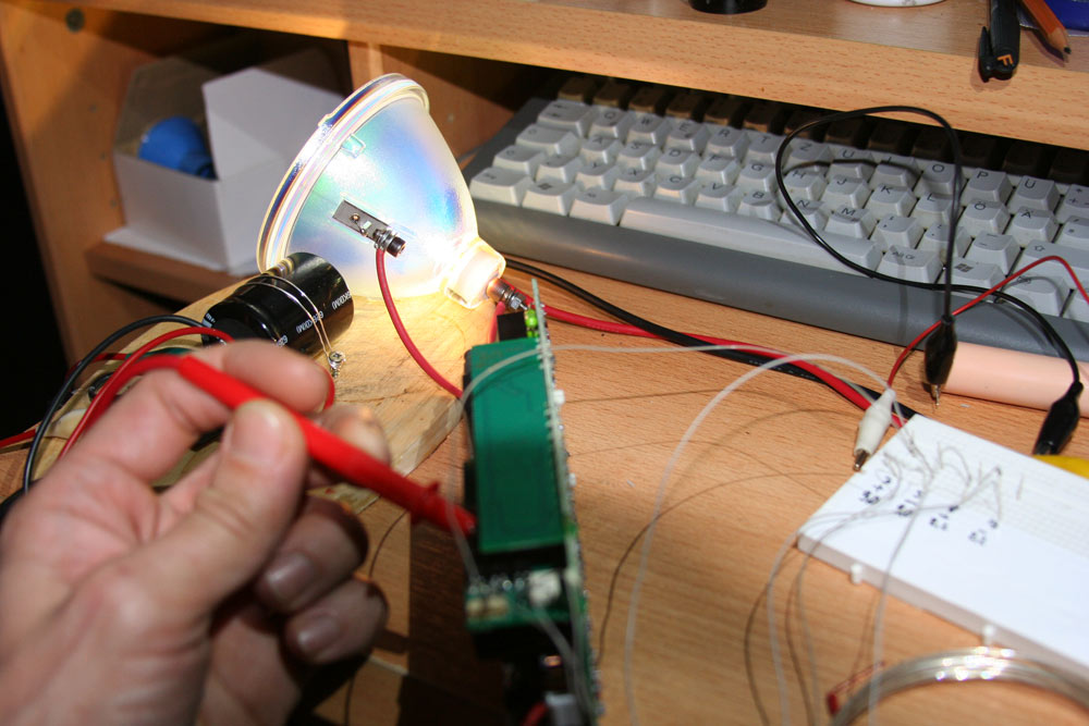
Voila:
uhprunning.jpg


Accidentally i kill my rectifier. Just for my safty i put a measure line betwen the 400v cap. But i forget and plug in, kill the fuse. :shakehead I think and hope its the rectifier...

Bevor it die, i measure 318 volt vdc out of the 230 volt here in germany.

If its work again with new diode the nice work with putting everything togheter starts. juhu... :whistle:


Daniel
 
Last edited:
Re: UHP Lamp Driver, help needed please (solved)

Great!

The formulas was based on the suggested drive current for the optocouplers. 9 V for an interface is in no way impossible, just very uncommon. Also, 1000 is probably 100 ohm (100*10^0) which would end up with ~3,3 V, which is a common interface voltage.
 
Re: UHP Lamp Driver, help needed please (solved)

Wow, it's great so see this being tried! Since you're sticking with the P-VIP built-in reflector, the reflector won't take real advantage of the arc's capability. Those reflectors are small, probably mid-grade at best, and many aren't even parabolic. You will have to find out if it's the parabolic version.

I hope you can post some beam shots. Great work!
 
Re: Cyclops 15MCP to 120 Watt UHP

Hi my Inspirator, :wave:


Yes i will Try a light with this bulb.
The reflektor is a parabolic one!
The beam is impressive with this stock reflector.

My plan is to use the reflektor from the Cyclops 15MCP, the Reflector Arc ratio is much better. From what i learnd here in CPF i get better trow with smallest lightsource to reflector size ratio.

I think about another high quality Parabolic, but without spending some hundred $ .
I find a german tanklight reflektor for 100usd but it has a 300mm diameter wich dont fit the host.
I think i test the stock reflector.

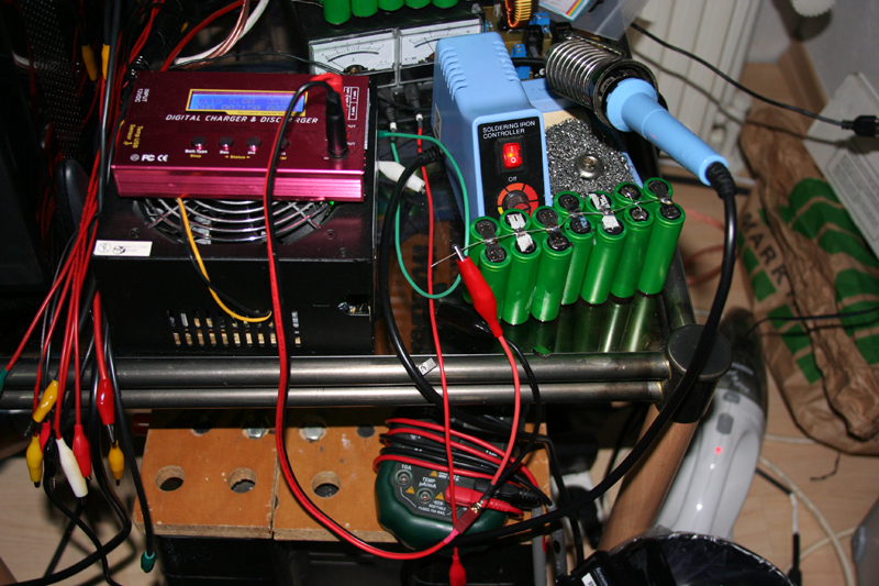
Right now ha have harvested the cells i want to use.
I know LiIon is not top level, lipo or better LiFePo is state of the Art. :)
This Cells are from Lenovo 10,8Volt 5200maH Pack so this cells are 3,6Volt 2600maH.

To even them out i solder them togheter and let them rest, then desolder.
Let them rest again and measure the Voltage.

Later this night the plan is to accomplish the light on workstation running from batteries.
I have this 150 Watt Converter, i want to test what works best 3 or 4 cells in series.

lenovo.jpg


But right now i do a balcony beamshoot with the stock UHP reflector. :whistle:


Daniel
 
Re: Cyclops 15MCP to 120 Watt UHP

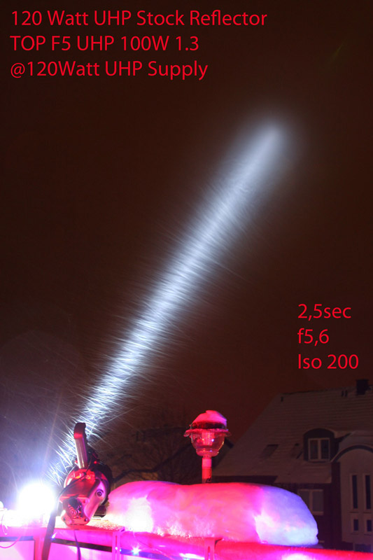
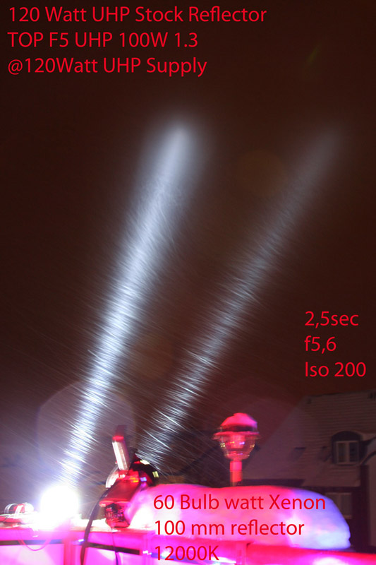
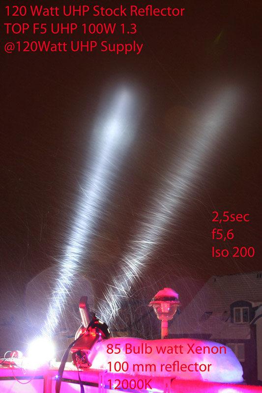
I do some comparison Beamshoots between my 12000K HID
and the bulb in its stock reflector. Running at my 230VAC Line converted to 320VDC.

Its a 100 Watt bulb running at this philips 120 watt supply, i have not measured the power consumption so far.
I will do this later while testing the best batterie configuration for the DC/AC converter.

Its on my balcony and we have middle light snow falling.

I like to go out to point on something with the UHP bulb,but its to cold.:candle: From balcony its not possible to many angry neighbours... :naughty:


All the data is written on the pictures, except i have running 3x 3watt red led emitters on my balcony for "cristmas illumination", means my balcony is permanently red flooded. For my fun... :crazy:


I Like the shoots because the beam zones are very good visible on the UHP.
The UHP is stock centered, the HID is manualy potted by me. Maybe a bit offcenter but still trow capable. Seperate tread for this light is HERE.

Thi Hid is still a beast but the UHP outperform easyly with the stock reflector. Like expected. The Hid shine to the right and the UHP to the left side they are not paralell. The beam of the UHP looks longer in real.

balconyb1.jpg


The HID is way overdriven, its a 35 watt china bulb at 60/85 watt, the colour will not stay at the 12000k. It must be white when overdriven from what i read.
The UHP is pretty white.
balconyb2.jpg


balconyb3.jpg


balconyb4.jpg


Daniel
 
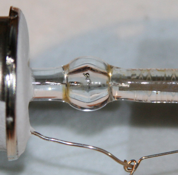
Accidently i break my UHP burner. :shrug:

I did not notice bevor i remove the burner from the reflector. I thought i have a good bulb and found one electrode broken. :thinking:

How can this be? To much movement on the hot bulb after i switsch it of last time?
closebrokenuhp.jpg


It was running till i switsch it of.
Now its potted in a H4 socket and as soon the light is ready i give some high voltage to this bulb again, just to see whats happen. :poof:

A used other one is in the mail. :D

Maybe anybody a hint how to connect the wires?
I use the "mechanical" solution, soldering does not work, for welding i dont have the capability and tools.


Daniel
 
Wow that's some nice clean while light output. I could imagine what a real reflector would do for that. Did you have active ventilation on the lamp. In projectors, cooling is maintained for a while even after the lamp is turned off, so maybe it simply melted even after it was turned off, because it was being moved around without cooling while still red hot.

Maybe anybody a hint how to connect the wires?
I use the "mechanical" solution, soldering does not work, for welding i dont have the capability and tools.

Why not solder? If the leads are too conductive to melt the solder, then just use a higher wattage soldering iron to overcome the heat dissipation.
 
Last edited:
Hm, I thought that solder will melt easyly that close to the lamp.

This burner died while iam still testing, the light will have no airflow in the reflector houseing. My plan is to put a fan in the rear of the thor host and blow trought the batteries and the power supplys to the original vents.


Do the great spotlights have airflow INSIDE the reflector around the burner?

best regards


Daniel
 
Top