Electrical isolation of P7 LED

WeatherB

Newly Enlightened
Joined
Jan 25, 2009
Messages
9
I am trying to mount my P7 LED onto a grounded (attached to negative terminal of battery) copper heatsink.

What I have been noticing is that everytime the metal "plate" at the bottom of the LED touches the heatsink, the LED turns off.

Do I need to somehow isolate the metal "plate" from the heatsink? This seems like a very stupid design.
 
yes - the design is very dumb in my opinion.

the bottom of the P7, the Slug, is also the + terminal
 
yes - the design is very dumb in my opinion.

the bottom of the P7, the Slug, is also the + terminal

Thanks for the quick reply.

Since I am using direct drive, I should be able to simply put the battery in the backwards and switch my wires around so that the heatsink is actually the positive.

Does the P7 have a negative and positive terminal like a traditional LED?
 
SSC LEDs have the slug conductive to positive. From what I've been able to gather, this is to improve heat transfer. I still wonder if it's worth the hassle though... couldn't it have been made conductive to negative?

It would probably be possible to rewire things so as to have a positively grounded flashlight body (and you would only need one wire to the LED), but there's a higher risk of shorts since all drivers have the outer contacts negative.

Edit: if you're direct driving then yes, it should be possible to do what you say.
The P7 has eight terminals. You can wire them in parallel (it behaves as if it has two) or in series.
 
Yup, its a PITA when that happens
One solution would be to use an anodized heatsink
but if you already have a raw heatsink then one thing you can do is to apply
a thin layer of AA to the bottom of the emitter, let it cure then apply another layer of AA to attach the emitter to the heatsink.
From what I understand, normally when using AA to stick the emitter onto the heatsink, you are only supposed to use as little as possible. Something
about using too much and lessening the heat conductivity.
So I dont know how much having two layers will effect it.
 
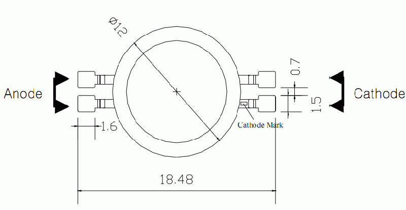
...Does the P7 have a negative and positive terminal like a traditional LED?


Yes, in one of the four terminals there is a little hole, this is the cathode ( - ) mark.


P7.gif


tl
 
The P7 has eight terminals. You can wire them in parallel (it behaves as if it has two) or in series.

That's the MC-E, not the P7. The other nice thing about the MC-E is the slug is isolated, so you can use the most thin layer of AA on a bare heatsink.
 
I am only using anodized aluminum heatsinks in the future. I have had too many problems getting the LED's isolated.

Your copper heatsink is great for absorbing heat, but it's not the easiest to work with unless you're using a star.
 
SSC LEDs have the slug conductive to positive. From what I've been able to gather, this is to improve heat transfer. I still wonder if it's worth the hassle though... couldn't it have been made conductive to negative?
That wouldn't help with the case where you have multiple emitters, and want them wired in series -- probably a more common case. You need a fully isolated emitter for that, or use an isolating star.

I actually slightly prefer the SSC way, as it does give you the option of high thermal conductivity or adding external isolation (at the cost of conductivity); when the slug is isolated internally, there's no way to get it back. OTOH, it is one more thing to worry about; maybe I'd be leaning the other way if my first build hadn't been a single-emitter.

It would probably be possible to rewire things so as to have a positively grounded flashlight body (and you would only need one wire to the LED), but there's a higher risk of shorts since all drivers have the outer contacts negative.
Yes, but if you're careful, you can do it. I did a 4D Mag P7 this way (I soldered the LED to the heatsink for minimum thermal resistance, but still used a redundant + wire anyway for electrical connection.) A +ground DD, of course, is trivial. You'll need to modify the tailcap spring as well, though, to make good contact; I can post pictures of mine if desired, when I get home tonight.
 
That's the MC-E, not the P7. The other nice thing about the MC-E is the slug is isolated, so you can use the most thin layer of AA on a bare heatsink.
Whoops. Sorry about that, haven't yet had the chance to play around with a P7 and thought both emitters used the same terminal design.

As for electrical insulation of a P4/P7, I've received a suggestion on another forum that seems good: mix a small amount of talcum powder with heatsink goop/epoxy and squish the result inbetween led and heatsink. If the heatsink is flat enough, this should provide both good heat transfer and thermal insulation, as the talcum particles keep the two surfaces apart enough that no contact occurs.
I haven't yet tested this, though.
 
I have reversed the polarity of the battery to overcome this problem.
I have also tried using a very thin layer of mica glued between the P7 and the slug with not heating issues at all.
 
Just use nail polish to isolate Led base, before applying AA, to much AA will decries heat transfer, I use this technique on many lights, and newer have problems.
 
Reversing the polarity worked perfectly. Didn't even have to play around with the springs.

Here is the final product. Added an aspheric lens to my TrustFire from Deal Extreme. I had to move the LED closer to the lens to get the correct focus.

P1000782.jpg


P1000784.jpg


P1000786.jpg


P1000788.jpg

P1000788.jpg
P1000786.jpg
P1000784.jpg
 
My all-time favorite for quick electrical insulation is clear nail polish. It's so thin that it provides almost no thermal insulation, but it'll block up to 12V (that I know of) with no problem at all.

It's basically the same stuff as the enamel on enameled wire.
 
Reversing the polarity worked perfectly. Didn't even have to play around with the springs.
Of course it worked. Haven't you ever watched an episode of Star Trek? Half the poop they have trouble with, they fix by reversing the polarity. (The other half they fix by re-routing the EPS grid around the ruptured plasma conduit -- just wait, it'll be an issue on CPF eventually.)

Of course, Star Trek is just science fiction -- you can tell it isn't realistic, because they never once solved their problem by just rebooting the ship's computer.
 
Last edited:
Top