jeffosborne
Enlightened
For a while now I have been using neutral-white Rebel LEDs to build small portable lights to use for photography. They tend to be used for table top photography or as fill-in lights for existing lighting, with 500 to 1000 lumen output. When the new high-CRI Rebel emitters became available recently, I was inspired to build a light bright enough to use with a diffuser or umbrella as a primary studio light. I made use of a suggestion made by CPF forum member JTR1962 to add cyan and red emitters to increase the CRI. Thanks, JTR1962!
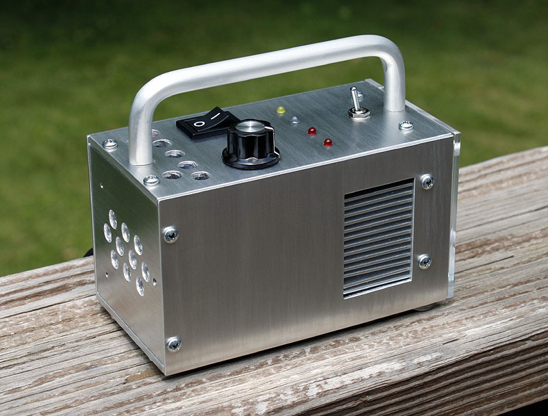
This new light uses 15 of the Rebel high-CRI (color rendition index) emitters, part LXM3-PW51, which have a typical CRI of 85. It also has two red and one cyan emitter to further boost the CRI. A toggle switch on top of the light sets the output to either 15 white emitters only, or 12 white with 2 red and one cyan emitter. I wanted to compare the difference that the color LEDs would render. The top panel includes a power on-off switch, rotary brightness dial, and four 3mm indicator LEDs: yellow power on, blue fan on, red battery low, and red overheat. The all-aluminum enclosure is 4.5" long, 2.5" wide, and 2.625" tall, less the feet and handle. It weighs 1.1 pounds. A lexan window covers and protects the emitters. All are hand made with simple tools. I did get a bench top drill press for Christmas last year (thanks Jim!) and that has improved my results over using a hand drill.
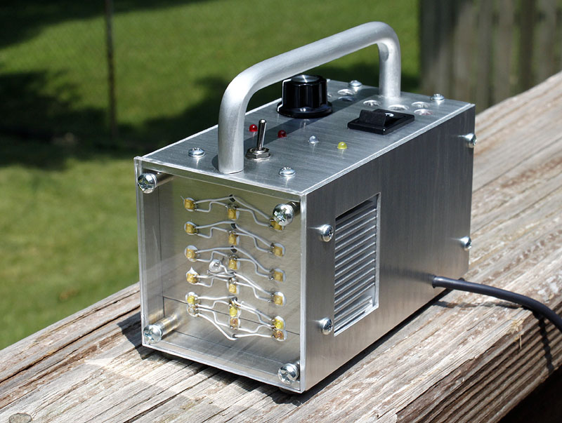
In all-white mode the lamp produces 2500 lumens at the emitters, according to the manufacturer's specs. With 12 white, 2 red, and 1 cyan, that drops to about 2250 lumens. I do not notice the brightness difference, and the color shift is slight but noticeable. The cyan and red LEDs are driven at 500ma maximum, all the others are driven at 850ma at full brightness. The light contains no batteries. It has a 6' power cord that plugs into either a battery pack or 12 volt DC power supply. At full brightness it draws 4 amps. The output is continuously variable with the potentiometer, but I tend to use it on full.
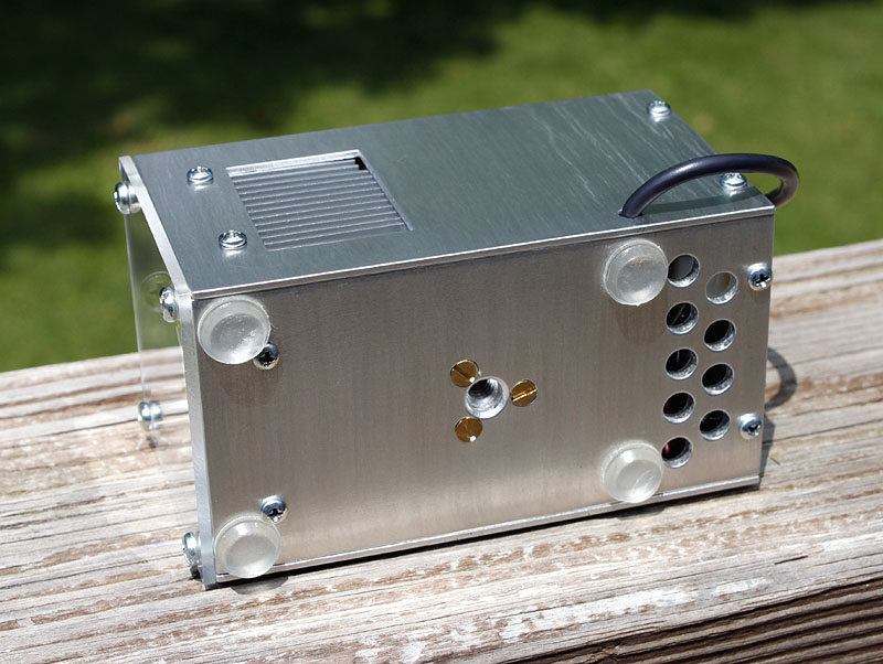
Both side panels have openings that allow air to exit when the fan is on. You can see the sides of the P4 heat sink fins there. The rear panel has several vent holes, and 3 small tapped holes used to mount the driver printed circuit board inside.
The bottom and top panels also have vent holes for incoming air. The hole near the bottom center has a threaded ¼" female light-stand fitting inside. My primary use of this light has been on a light stand, with a reflector attached. The clear rubber feet are 3M self-adhesive bumpers.
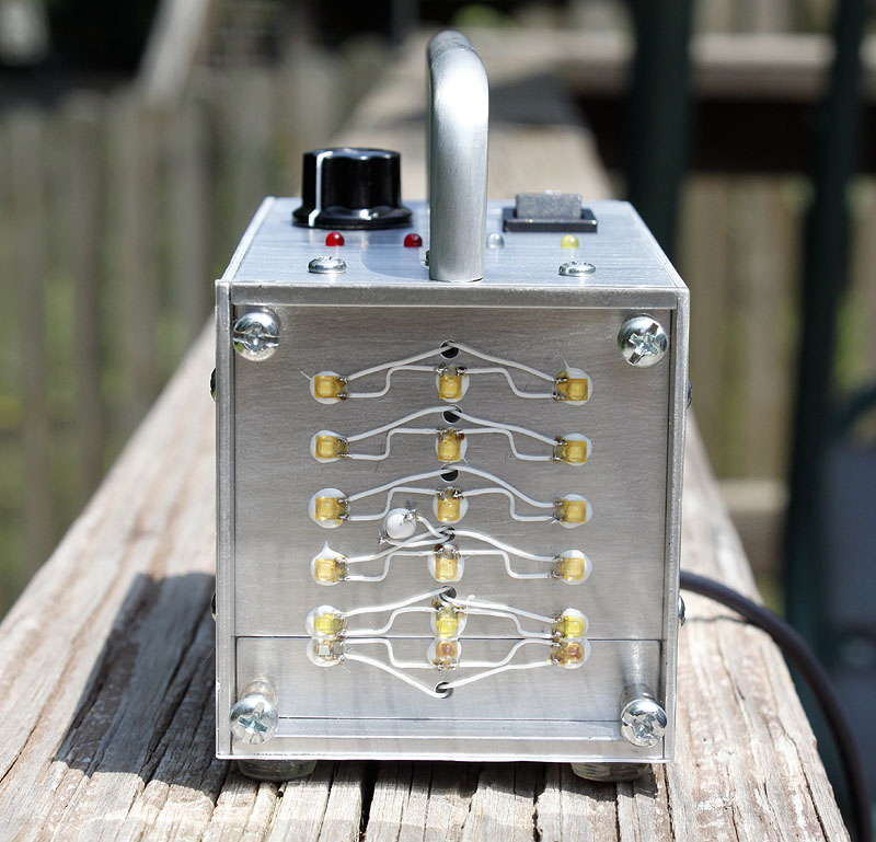
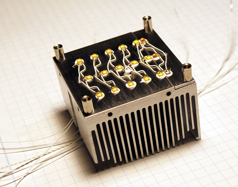
The emitters are wired as six sets of three in series. The cyan and red emitters are at the bottom row.
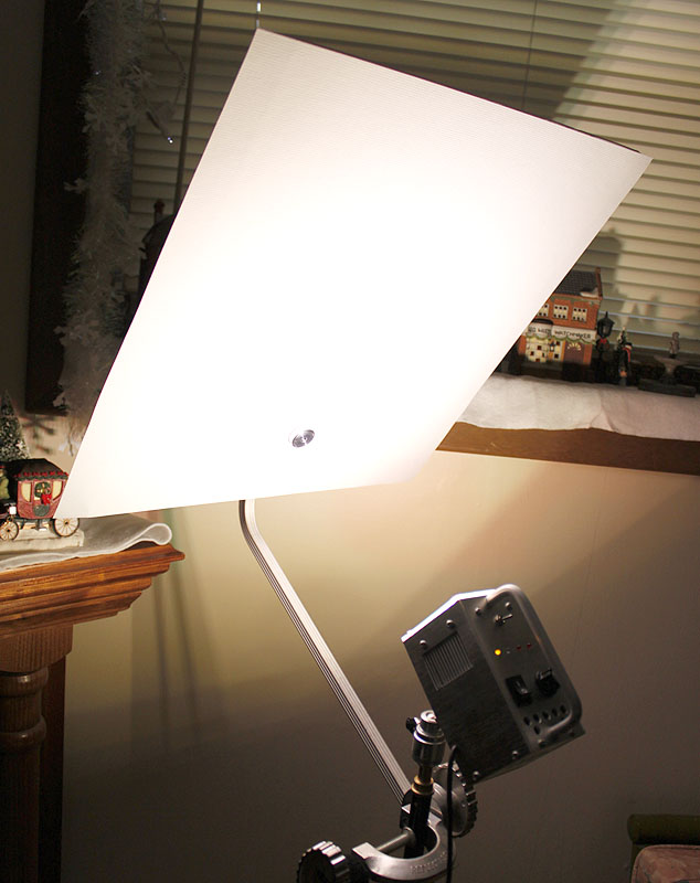
The first reflector I used with the light was an 18x18" sheet of textured Epson Heavyweight Matte paper mounted to foam core board. It made a pleasing soft light, but was not too efficient
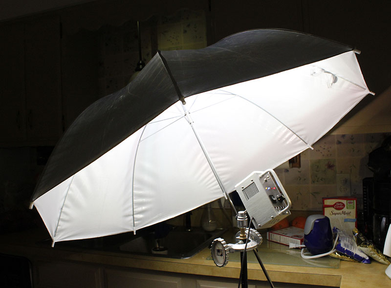
Next I tried a light weight 48" umbrella reflector made by Paul C. Buff Co. with very good results.
Here's a portrait made with only the high-CRI light. The shadows are very soft, and the skin tones look natural. The light is set to include the red and cyan emitters for this shot.

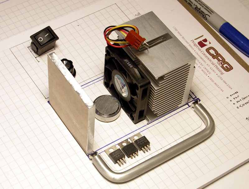
Building the light was fun, and a challenge. With about 40 watts to dissipate, I decided to use a large CPU heat sink and a 50mm, 12 volt cooling fan. Light-stand mounting is a must for studio lights, so a round aluminum adapter with the proper fitting is secured to the bottom. It is next to the fan below. My on-off switch and dimming potentiometer would need to be accommodated, as well as the control electronics, fuse holder, and some wiring. The handle was left over from a previous project, and it is included to keep the top side controls from being inadvertently reset. The plan is to use a ¼" thick aluminum rear panel, cut to the same dimensions as the heat sink, so I can drill and tap holes in each to mount the side panels.
This is 30-06 aluminum, recommended by the salesman at the local sheet metal shop. Not too soft, but not too brittle either. It was easy to work with. I used 1/16" thick pieces for the side panels, and 1/8" thick pieces for the top and bottom panels.
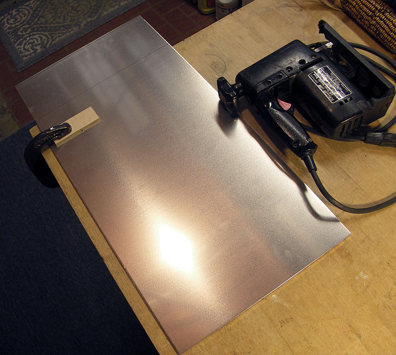
The heavier 1/8" thick pieces at the top and bottom help to make a sturdy enclosure. Once the holes are located and marked, I like to use a center punch to keep my drilling on track. Lots of filing is required after the pieces are cut and drilled, to smooth edges and adjust dimensions.
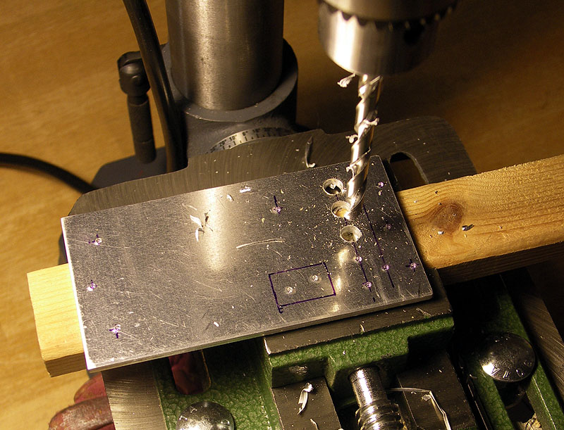
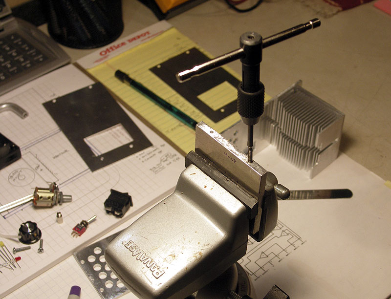
The large heat sink and rear panel are drilled and tapped to accept #4-40 screws, which secure the top, bottom, and side panels.
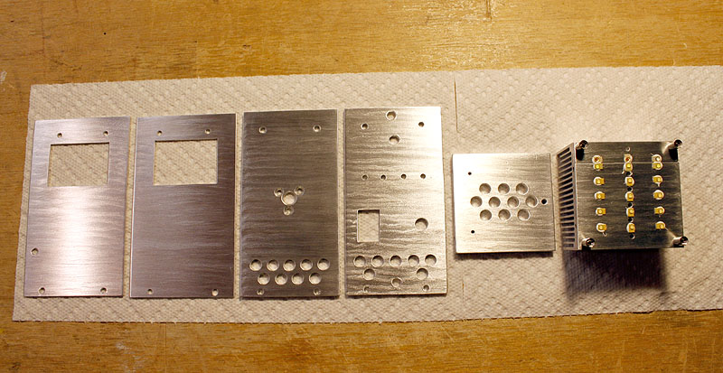
I use a grit impregnated nylon brush on my hand drill to smooth and finish the pieces. Here are all the enclosure pieces, which have been washed to remove any aluminum dust.
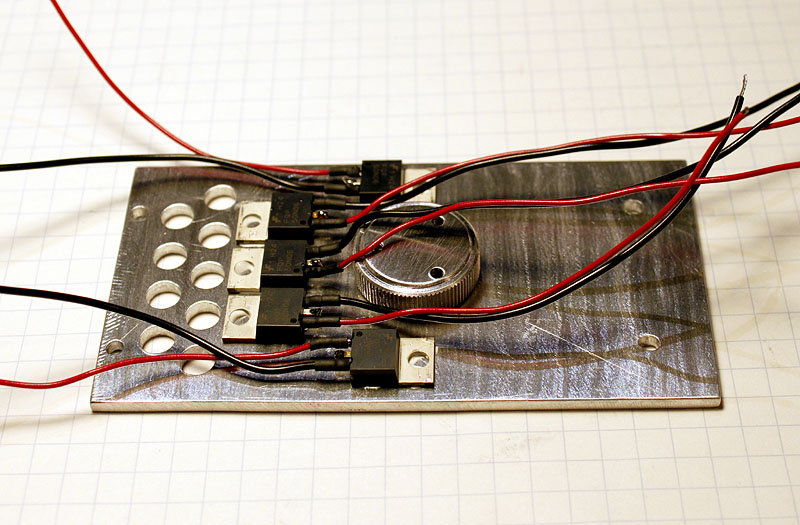
The bottom panel has 5 MOSFET transistors mounted with arctic alumina epoxy. Each transistor is part of a circuit driving 3 LEDs in series. The round aluminum piece in the center is the light-stand fitting.
The LEDs are mounted directly to the heat sink with thermal epoxy. Near to the center a 50K ohm thermistor is also mounted. When the temperature reaches 140 degrees, the cooling fan comes on. If the thermistor reaches 210 degrees, the control circuitry shuts off the lights. If the fan were to fail this would protect the LEDs from overheating. The threaded spacers mounted to the corners are used to secure the lexan window.
Oh, I know it looks like a lot of wires, but it is all manageable. The 6 white wires with red ends will all be cut as short as possible and connected to one fat 16 gauge wire that connects directly to the power on-off switch. The other white wires attach to either the toggle switch or one of the transistors below. The braided wire set is the thermistor leads.
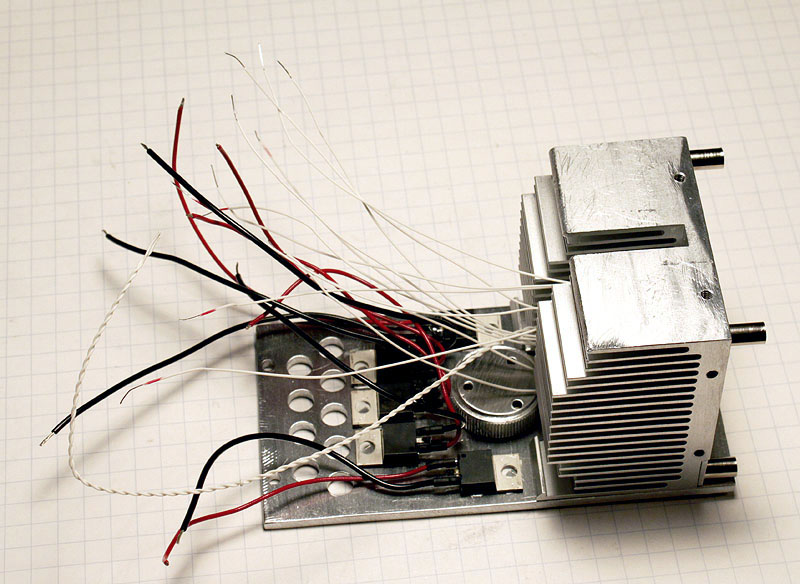
With additional assembly completed, we still have lots of wires. We added wires from the indicator LEDs and the potentiometer, and now all of these conductors will attach to the control PC board.
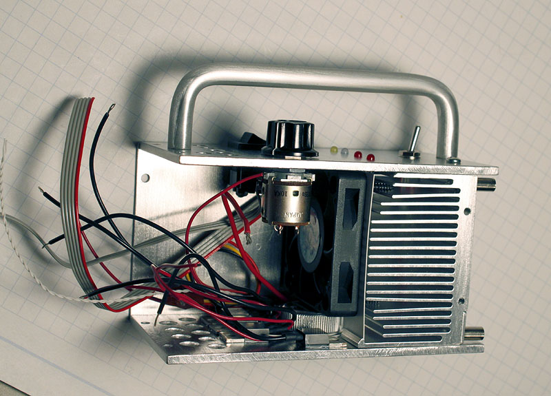
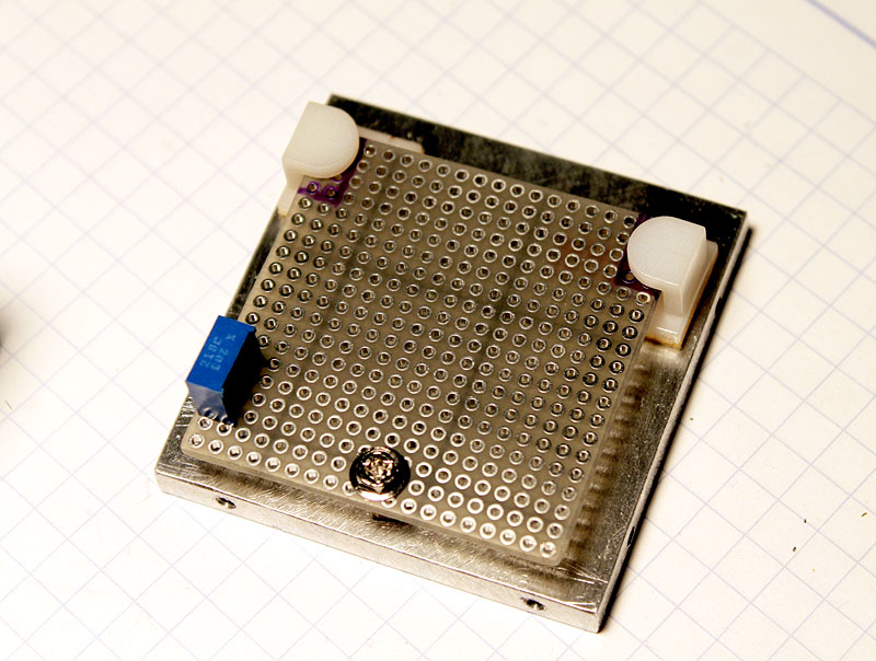
The control circuitry resides on a small piece of prototyping board with plated through holes at .1" spacing. The board slides into two nylon fittings at one end, and is secured with a single screw into a threaded spacer at the other end. This arrangement makes it easy to get to the PC board - I need only to remove one side panel and one screw to slide it out.
Laying out and soldering the components to the PC board is made easier by having the schematic for the circuit drawn around a physical layout of the two comparator ICs. These quad comparators ICs are LM239N.
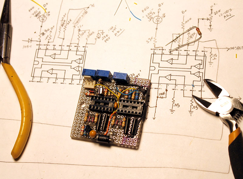
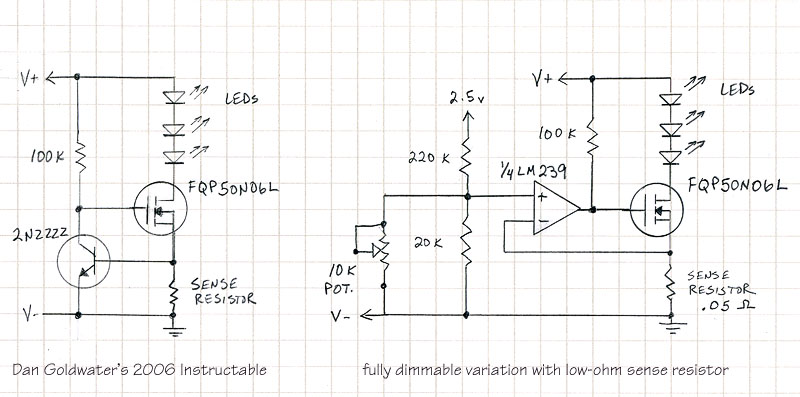
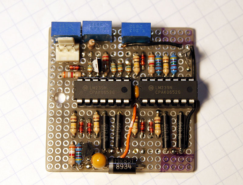
Five of the eight comparators are used for the linear current regulators driving the LEDs. Two comparators are used with the thermistor to turn on the fan as needed, and shut the light off if overheated. And one comparator looks at the incoming supply voltage and lights the 'low battery' indicator if it drops below 10 volts. My previous lights have used a small signal transistor across the sense resistor to regulate the MOSFET, which requires a .5 volt drop across the sense resistor – not very efficient. Here the small signal transistor is replaced with a comparator, so my sense resistor can be very low ohm - .05 ohm 1% is used. The voltage drop across this resistor is only .045 volts with the maximum 850ma current flow – much more efficient. The blue components at the top are trim potentiometers for the adjustment of low voltage, fan on, and overheat detection.
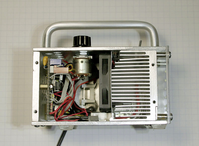
This is the completed unit with one side panel removed. The enclosure size worked out well for the space required. After making initial adjustments, it has worked without a hitch.
The quality of light is improved over my other standard neutral-white lights, for most subjects. I really notice the skin tones, lips, and any warm or brown tone to be improved. This has been a worthwhile project!
Before I built the light, I knew I would need a larger battery pack for portable use, so I built one in a Bud Industries NEMA rated, waterproof transparent enclosure, with nine 18650 Li-Ion calls in a 3S-3P configuration. It powers the new light for almost 2 hours on full brightness.
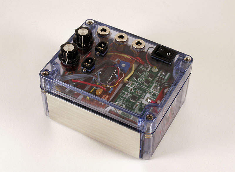
This pack has 3 switched battery outputs and two variable regulated outputs for 0 to 850ma. I will post this project separately in the batteries section of the forum.
Keep your batteries charged!
Jeff O.
This new light uses 15 of the Rebel high-CRI (color rendition index) emitters, part LXM3-PW51, which have a typical CRI of 85. It also has two red and one cyan emitter to further boost the CRI. A toggle switch on top of the light sets the output to either 15 white emitters only, or 12 white with 2 red and one cyan emitter. I wanted to compare the difference that the color LEDs would render. The top panel includes a power on-off switch, rotary brightness dial, and four 3mm indicator LEDs: yellow power on, blue fan on, red battery low, and red overheat. The all-aluminum enclosure is 4.5" long, 2.5" wide, and 2.625" tall, less the feet and handle. It weighs 1.1 pounds. A lexan window covers and protects the emitters. All are hand made with simple tools. I did get a bench top drill press for Christmas last year (thanks Jim!) and that has improved my results over using a hand drill.

In all-white mode the lamp produces 2500 lumens at the emitters, according to the manufacturer's specs. With 12 white, 2 red, and 1 cyan, that drops to about 2250 lumens. I do not notice the brightness difference, and the color shift is slight but noticeable. The cyan and red LEDs are driven at 500ma maximum, all the others are driven at 850ma at full brightness. The light contains no batteries. It has a 6' power cord that plugs into either a battery pack or 12 volt DC power supply. At full brightness it draws 4 amps. The output is continuously variable with the potentiometer, but I tend to use it on full.
Both side panels have openings that allow air to exit when the fan is on. You can see the sides of the P4 heat sink fins there. The rear panel has several vent holes, and 3 small tapped holes used to mount the driver printed circuit board inside.

The bottom and top panels also have vent holes for incoming air. The hole near the bottom center has a threaded ¼" female light-stand fitting inside. My primary use of this light has been on a light stand, with a reflector attached. The clear rubber feet are 3M self-adhesive bumpers.

The emitters are wired as six sets of three in series. The cyan and red emitters are at the bottom row.

The first reflector I used with the light was an 18x18" sheet of textured Epson Heavyweight Matte paper mounted to foam core board. It made a pleasing soft light, but was not too efficient

Next I tried a light weight 48" umbrella reflector made by Paul C. Buff Co. with very good results.

Here's a portrait made with only the high-CRI light. The shadows are very soft, and the skin tones look natural. The light is set to include the red and cyan emitters for this shot.

Building the light was fun, and a challenge. With about 40 watts to dissipate, I decided to use a large CPU heat sink and a 50mm, 12 volt cooling fan. Light-stand mounting is a must for studio lights, so a round aluminum adapter with the proper fitting is secured to the bottom. It is next to the fan below. My on-off switch and dimming potentiometer would need to be accommodated, as well as the control electronics, fuse holder, and some wiring. The handle was left over from a previous project, and it is included to keep the top side controls from being inadvertently reset. The plan is to use a ¼" thick aluminum rear panel, cut to the same dimensions as the heat sink, so I can drill and tap holes in each to mount the side panels.

This is 30-06 aluminum, recommended by the salesman at the local sheet metal shop. Not too soft, but not too brittle either. It was easy to work with. I used 1/16" thick pieces for the side panels, and 1/8" thick pieces for the top and bottom panels.

The heavier 1/8" thick pieces at the top and bottom help to make a sturdy enclosure. Once the holes are located and marked, I like to use a center punch to keep my drilling on track. Lots of filing is required after the pieces are cut and drilled, to smooth edges and adjust dimensions.

The large heat sink and rear panel are drilled and tapped to accept #4-40 screws, which secure the top, bottom, and side panels.

I use a grit impregnated nylon brush on my hand drill to smooth and finish the pieces. Here are all the enclosure pieces, which have been washed to remove any aluminum dust.

The bottom panel has 5 MOSFET transistors mounted with arctic alumina epoxy. Each transistor is part of a circuit driving 3 LEDs in series. The round aluminum piece in the center is the light-stand fitting.

The LEDs are mounted directly to the heat sink with thermal epoxy. Near to the center a 50K ohm thermistor is also mounted. When the temperature reaches 140 degrees, the cooling fan comes on. If the thermistor reaches 210 degrees, the control circuitry shuts off the lights. If the fan were to fail this would protect the LEDs from overheating. The threaded spacers mounted to the corners are used to secure the lexan window.

Oh, I know it looks like a lot of wires, but it is all manageable. The 6 white wires with red ends will all be cut as short as possible and connected to one fat 16 gauge wire that connects directly to the power on-off switch. The other white wires attach to either the toggle switch or one of the transistors below. The braided wire set is the thermistor leads.

With additional assembly completed, we still have lots of wires. We added wires from the indicator LEDs and the potentiometer, and now all of these conductors will attach to the control PC board.

The control circuitry resides on a small piece of prototyping board with plated through holes at .1" spacing. The board slides into two nylon fittings at one end, and is secured with a single screw into a threaded spacer at the other end. This arrangement makes it easy to get to the PC board - I need only to remove one side panel and one screw to slide it out.

Laying out and soldering the components to the PC board is made easier by having the schematic for the circuit drawn around a physical layout of the two comparator ICs. These quad comparators ICs are LM239N.

Five of the eight comparators are used for the linear current regulators driving the LEDs. Two comparators are used with the thermistor to turn on the fan as needed, and shut the light off if overheated. And one comparator looks at the incoming supply voltage and lights the 'low battery' indicator if it drops below 10 volts. My previous lights have used a small signal transistor across the sense resistor to regulate the MOSFET, which requires a .5 volt drop across the sense resistor – not very efficient. Here the small signal transistor is replaced with a comparator, so my sense resistor can be very low ohm - .05 ohm 1% is used. The voltage drop across this resistor is only .045 volts with the maximum 850ma current flow – much more efficient. The blue components at the top are trim potentiometers for the adjustment of low voltage, fan on, and overheat detection.

This is the completed unit with one side panel removed. The enclosure size worked out well for the space required. After making initial adjustments, it has worked without a hitch.

The quality of light is improved over my other standard neutral-white lights, for most subjects. I really notice the skin tones, lips, and any warm or brown tone to be improved. This has been a worthwhile project!
Before I built the light, I knew I would need a larger battery pack for portable use, so I built one in a Bud Industries NEMA rated, waterproof transparent enclosure, with nine 18650 Li-Ion calls in a 3S-3P configuration. It powers the new light for almost 2 hours on full brightness.

This pack has 3 switched battery outputs and two variable regulated outputs for 0 to 850ma. I will post this project separately in the batteries section of the forum.
Keep your batteries charged!
Jeff O.


 :twothumbs
