KD MC-E series driver?

Techjunkie

Enlightened
Joined
Nov 16, 2007
Messages
943
Location
in the brightly lit suburbs of NYC (Long Island)
Does anyone have any experience with this product from KD?:

http://www.kaidomain.com/ProductDetails.aspx?ProductId=9265

Its title seems far too good to be true... drives an MC-E in series at 1.3A and takes input from 3V-26V.

Doesn't seem possible.

If anyone here has any info or direct experience, please reply. I've searched CPF for MC-E driver and KD and the PID but haven't found anything. Sometimes Jerry posts in the marketplace about new products but I haven't seen anything there either. Thanks.
 
Last edited:
KD ProductID=9534 seems to have a bad reputation on CPF for excessive heat and early failure. The Shining Beam driver is an AMC7135-based driver, and thus different from a buck driver.

Re: KD ProductID=9265, I don't know what a "series PCB" driver means. I also see that the link claims that the board is 20mm, which is 3mm larger than the usual 17mm diam board used in P60 drop-ins.

These operating voltage ranges typically refer to the voltage range for the buck IC. Pretty clearly, if you tried to drive a 4S or 2S2P MC-E at 3V, the LED wouldn't even light up.

The Shoppe's Shark Buck max rating is 3V-25V. TaskLED's bFlex is rated from 4V-25V. Both boards are similar in size to KD9265. So the KD9265 specs are not unheard-of. The notable difference is price.

In 17mm, KD1640 works well driving a 2S2P MC-E at 1.4A total drive current. You need to mod the board slightly with the appropriate sense resistor values to change the output from 1A to 1.4A.
 
Last edited:
Okies on the KD driver being NG.... didn't notice that the SB driver wasn't a buck driver.... [still learning all the terms]. I see what you mean about cost, vs. say a SS GD1000 driver.

Could KD mean the driver chips are in "series" vs. parallel? I thought that most of the 7135 based drivers were parallel. Not sure what the advantage of series vs. parallel unless it has to do w/ the regulation range rather than the drive current.
 
Last edited:
Looked at the link you posted, found similar P7 driver, should work w/ MC-E

http://www.kaidomain.com/ProductDetails.aspx?ProductId=9534

Shining Beam has a similar driver too.
http://www.shiningbeam.com/servlet/the-132/3-dsh-Mode-Regulated-Circuit-Board/Detail

Lower V driver than the KD you posted [agree, the V range seems unlikely] and 1.3A is underdrive for MC-E....

Not just looking for any step-down driver for MC-E. Was intrigued by this driver because of low input V and mention of serial. I've yet to see a cheap boost (or supposedly buck/boost in this case) driver for MC-E (or P7)

1.3A would actually be way overdrive for a 4S wired MC-E (700ma would be more like it). It would be almost perfect drive current for an MC-E wired 2p2s, but there was no mention of that.


...Re: KD ProductID=9265, I don't know what a "series PCB" driver means. I also see that the link claims that the board is 20mm, which is 3mm larger than the usual 17mm diam board used in P60 drop-ins.

These operating voltage ranges typically refer to the voltage range for the buck IC. Pretty clearly, if you tried to drive a 4S or 2S2P MC-E at 3V, the LED wouldn't even light up.

The Shoppe's Shark Buck max rating is 3V-25V. TaskLED's bFlex is rated from 4V-25V. Both boards are similar in size to KD9265. So the KD9265 specs are not unheard-of. The notable difference is price.

I've sent email to Jerry to see if he has any information. What makes this driver interesting to me is the mention of "series" as opposed to the sister item (http://www.kaidomain.com/ProductDetails.aspx?ProductId=9264) which is labeled parallel with different Vin and different drive current.

I suspect you are correct in thinking the Vin is not specific to the application the title mentions (MC-E series), but is the entire Vin range of the chipset used to regulate current to the Iout described.

I would have been very pleased to learn this was a buck/boost driver capable of boosting from only 3Vin, but that's as I said earlier, too good to be true.

...KD1640 works well driving a 2S2P MC-E at 1.4A total drive current. You need to mod the board slightly with the appropriate sense resistor values to change the output from 1A to 1.4A.

That's good to know. I actually have one of those on hand. Would you happen to know exactly what to resistor change and to what value?
 
The problem I've seen with KD's web site is that the information is often confusing and-or erroneous. The images of those two boards (KD9264 and KD9265) look exactly the same, so which is it? Does the "parallel" board have a different voltage range and drive current vs the "series" board"? Or are they the same board? Unfortunately, with the KD web site, you can't tell. Then, they also scratch off the identifying marks from the DC-DC converter IC, so you can't go to the datasheets for any guidance either.

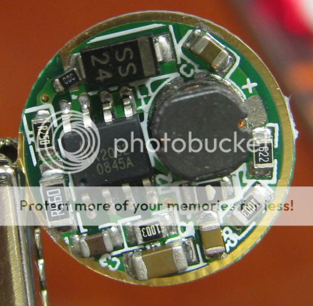
For the KD1640 driver, configure the sense resistors (the two SMD resistors to the left of the AX2002 buck IC) as shown here:
TLST5driver.jpg


The stock driver uses an R220 resistor where you see the R560, and the spot where you see the R250 above is empty. The result will be a nominal 1445mA out.
 
For the KD1640 driver, configure the sense resistors (the two SMD resistors to the left of the AX2002 buck IC) as shown here:
TLST5driver.jpg


The stock driver uses an R220 resistor where you see the R560, and the spot where you see the R250 above is empty. The result will be a nominal 1445mA out.

Thanks! If I can find the required resistors, then I'll have a driver suited to run a 2p2s MC-E from 2-4 IMR cells or 3-5 LiFePO4 cells. 2 IMRs would stay in regulation for most of the charge, but not all of it, and IMR C's are overkill for the single MC-E torch I'm concentrating on here, but I'm sure this will come in handy in a future project.
 
With this driver, I an driving a 2S2P MC-E using 2x18650. Some bench power supply testing seems to show that the driver will run in regulation at as low as 7V input, so by the time your 2xLi-ion cells drop to 3.5V each, it would be time to recharge them anyway. 3xLi-ion looks like it would also work well. I am hesitant to recommend 4xLi-ion. The bench power supply tests showed an odd driver behavior above 12V input.
 
Turns out I didn't have a kennan (KD 1640) after all. I had a similar but different DX driver: http://www.kaidomain.com/ProductDetails.aspx?ProductID=1640 . I think it uses the same IC, but performs voltage regulation instead of current regulation (product page shows different current for P4 vs. Q5). If I'm right about that then I can't run an MC-E 4S from it.

I did discover something else that's sort of relevant to running an MC-E in series from a two lithium battery config. There's chatter in the DX product forum about the 5*Cree 5-mode driver indicating that it is not voltage regulated to 17.5V as the product page seems to indicate, but is in fact current regulated to 800mA. One of the posters reported using it for 4 CREEs in series. If it's diameter and height fit, I could possibly use that $4 driver to use a CREE MC-E 4s board with two LiFePO4 cells.

This is still all way of topic from what drew me to the KD driver this thread is actually about though. The allure of the product title for me was in initially thinking it could drive a quad-die emitter from only 3V. It would have been fantastic to be able to drive an MC-E from only two NiMH C cells. (I know, that would require 4+ amp draw from the batteries.)
 
Hi,guys.
is a good discussion but i have a problem... haven't find a good buck led driver for mc-e led .... i need to connect it in series and i have a lipo 4s 3300mah...if i connect 4 led in series for 14v , lipo when is full charged is 16,8v, led calc show me a 4ohm 2watt resistor...is a good idea?ps lipo alarm is set to 3.2v/cell
dx and kd have anything to help me...
 
Top