MagAA OFC K2 TFFC Mod

darkzero

Flashaholic* ,
Joined
Oct 7, 2003
Messages
4,459
Location
SoCal
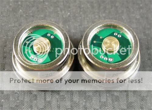
Here's a repair that I was asked to document. First time I've used one of these & got to see one in person. Very nice heatsink & I'm sad to have missed out on them. :ohgeez:

Hope the owner enjoys! :wave:


-mariposaoyaka's OFC MiniMag AA heatsink
-K2 TFFC TVOD
-GD1000


Copper corrodes & oxidizes very easily. Good thing it cleans up easy so I started out by cleaning it up & removing left over epoxy.
Img_5120.jpg


IMG_5144.jpg


IMG_5147.jpg


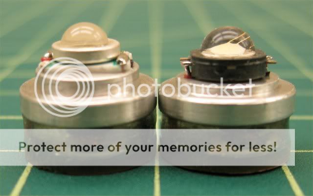
Repositioned the inductor inwards to allow better fitment in the OFC's can.
IMG_5151.jpg


Added a brass contact for better wear as with all my builds when applicable.
Img_5163.jpg


Trimmed the K2 TFFC so the owner would have no issue installing & removing the pill with the retaining ring from one Mag to another.
Img_5169.jpg


Img_5171.jpg


Img_5180.jpg


She's a screamer! All my MagAAs are bored out for use with various 20mm reflectors. Because of the height of the OFC it can not be used with a 20mm reflector & must be used with a reflector such as a McR-18 or IMS/Khatod17.

So here's my test setup lego'd from two of my most favorite Mags beautifully machined by Mirage_Man using a AA-to-C adapter (I had to bore out to fit the OFC). 1x AW14500

Img_5194.jpg


Img_5190.jpg


Img_5183.jpg


Thanks for looking! :grin2:
 
If anyone has a spare OFC heatsink they're willing to sell please let me know! :popcorn:
 
Any details on the brass contact that you add? Looks much neater than the solder blob I put on my Madmax... The C head is huge on the cut down mag body! Ever try one of the BHCs from H22A?
 
Thanks fellas, I always wondered what I was going to do with that adapter.


Any details on the brass contact that you add? Looks much neater than the solder blob I put on my Madmax... The C head is huge on the cut down mag body! Ever try one of the BHCs from H22A?

Nothing special, just a tab cut from a brass rod. I use brass cause it can be soldered on. I got tired of the solder blobs going flat on my MagAA sandwiches & Mcluxs when these were my EDCs. Got the idea from Larry (TVODRD) many years ago who sent me some tiny brass tabs when he sent me the last of Larry lights. I still have those too. :grin2:


Here's a side view of some other LEs (these were "hand" cut before I started doing them on the lathe).
Img_7655.jpg
 
Last edited:
The brass contact is a great idea. I'll have to borrow that one. I could probably also use this trick on DMag mods for the spring contact that is otherwise slightly recessed by the plastic switch housing. Moving the inductor inward is above and beyond. IIRC, the GD fits without doing that, but it is off-center slightly. I doubt there is any functional difference, but certainly a perfectly centered driver under the heat sink shows total perfection. Bravo!

A major shortcoming of the mariposaoyako heat sink IMO is the slightly undersized feed holes for the hookup wires to the LED. In fact, you can see slight threading indentations in the red wire in your side view photo (7th from the top) of the assembled module. You can also see the retaining ring's threads pressing against the red wire's insulation in the photo 6th from the top. When I used 24 ga wire, the retaining ring threads were cutting the wire's Teflon insulation. I've gone with 26 ga because of that.

Have you tested extended runs in a 2xAA Mini Mag? I am very conservative and went with a BBNG400 to avoid any heat issues.

Admittedly, however, I also built a direct-drive Mini Mag using one of mariposaoyako's heat sinks (so much for being conservative). It works quite well for short runs, but I haven't tried any extended runs yet. I have an old Tacstar 1xAA extender for the Mini Mag, turning the light into a 3xAA model. With 3xNiMH, I get about 1.05A draw at the tail, which is just about perfect for the Cree XR-E Q5 I'm using. 2xAA is rather dim (I get about 115mA at the tail).
 
Last edited:
The brass contact is a great idea. I'll have to borrow that one. I could probably also use this trick on DMag mods for the spring contact that is otherwise slightly recessed by the plastic switch housing.

If you are capable of doing so, you can modify the switch like this which will allow contact with flat top cells:
Img_3604.jpg


Moving the inductor inward is above and beyond. IIRC, the GD fits without doing that, but it is off-center slightly. I doubt there is any functional difference, but certainly a perfectly centered driver under the heat sink shows total perfection. Bravo!

Yes, that is exactly why I repositioned the inductor. Doing so also creates another issue where the transistor will short on the can if it is not insulated.


A major shortcoming of the mariposaoyako heat sink IMO is the slightly undersized feed holes for the hookup wires to the LED. In fact, you can see slight threading indentations in the red wire in your side view photo (7th from the top) of the assembled module. You can also see the retaining ring's threads pressing against the red wire's insulation in the photo 6th from the top. When I used 24 ga wire, the retaining ring threads were cutting the wire's Teflon insulation. I've gone with 26 ga because of that.


I think the size of the holes are good. Any larger & the holes may be partially covered by certain emitters anyway. I use 26 awg in most of my builds which is my personal preference & is more than sufficient in the mods I do even at 2A+ (except for the high power mods). I don't see a need to use oversized wire or excessive lengths. I also use 19 strand wire instead of 7 strand which also offers better flexability.

Anyways, the 26 awg wire I use fits through the holes with the retaining ring in place very freely without any issue. The impression from the threads of the retaining ring you see is because of the wider package of the K2 which pushes the wire outwards slightly towards the top at the connections. If it were a Seoul or Luxeon or any other LED with a narrower package this would not be an "issue". I don't consider it an issue with this as it is barely touching only when the retaining ring is initially screwed on. There is no resistance felt & no additional impressions every time the retaining ring is unscrewed/screwed on so there shouldn't be a worry of the threads cutting further into the the jacket to pose an issue. Plus the teflon jacket is pretty strong. If it ever does I fully warranty my work. Good attention to detail BTW, I like that. :thumbsup:


Have you tested extended runs in a 2xAA Mini Mag? I am very conservative and went with a BBNG400 to avoid any heat issues.

Admittedly, however, I also built a direct-drive Mini Mag using one of mariposaoyako's heat sinks (so much for being conservative). It works quite well for short runs, but I haven't tried any extended runs yet. I have an old Tacstar 1xAA extender for the Mini Mag, turning the light into a 3xAA model. With 3xNiMH, I get about 1.05A draw at the tail, which is just about perfect for the Cree XR-E Q5 I'm using. 2xAA is rather dim (I get about 115mA at the tail).


I used to build a lot of sandwiches. I've never recommend a sandwich higher than 750ma (many have asked) & even at that it is pushing it. In hopes for better thermal management I used to build heatsinked sandwiches but still the MagAA just doesn't have the mass. http://www.candlepowerforums.com/vb/showthread.php?p=2491423#post2491423

Img_2324.jpg


With a GD917 heatsinked sandwhich 7 min is pretty much the continuous runtime you can get before the MagAA starts to become uncomfortable to hold. This was in a finned MagAA which really doesn't make that much of a difference since the heat transfer between the threads to the head is poor anyway.

I tested this one in my setup pictured & heat is not an issue. However much of the heat is being disappated by the large mass of the AA-to-C adapter. I also ran it for 15 minutes without the head & I must say the OFC does a great job at absorbing the heat. It was pretty warm but not uncomfortable to hold as with the GD917 heatsinked sandwich at 7 mins in a finned 1xAA. The end at the OFC was pretty toasty though. I wouldn't be grabbing for this one (with a standard MagAA head) to keep me safe through the night but it sure is one of the nicer MagAA mods I have built.
 
If you are capable of doing so, you can modify the switch like this which will allow contact with flat top cells:
Img_3604.jpg

Yes, I know about turning down the plastic housing. It seems a lot simpler to lengthen the spring by adding a spacer to the end.

Yes, that is exactly why I repositioned the inductor. Doing so also creates another issue where the transistor will short on the can if it is not insulated.

What transistor? The IC marked "ACM"? I'm pretty sure that's a current sense amplifier.

I think the size of the holes are good. Any larger & the holes may be partially covered by certain emitters anyway. I use 26 awg in most of my builds which is my personal preference & is more than sufficient in the mods I do even at 2A+ (except for the high power mods). I don't see a need to use oversized wire or excessive lengths. I also use 19 strand wire instead of 7 strand which also offers better flexability.

24 gauge is a tight fit through the OFC heat sink. I like to have the option of using the thicker gauge.

I used to build a lot of sandwiches. I've never recommend a sandwich higher than 750ma (many have asked) & even at that it is pushing it. In hopes for better thermal management I used to build heatsinked sandwiches but still the MagAA just doesn't have the mass.

Thanks.
 
Yes, I know about turning down the plastic housing. It seems a lot simpler to lengthen the spring by adding a spacer to the end.

Makes sense, just keep in mind never to pop that spring out on the D switch, it's not easy to get it back in without bending it out of shape.


What transistor? The IC marked "ACM"? I'm pretty sure that's a current sense amplifier.

Yes. I'm no electronic engineer, I'm bad at idenitifying components sometimes, I leave that up to you. I can just do the rework. :grin2:


24 gauge is a tight fit through the OFC heat sink. I like to have the option of using the thicker gauge.

Why? No sense in pushing 2A in one of these & with the short length of wire 26AWG would still be good for over 2A.
 
Thanks for the tip on not popping out the Mag switch spring. I've been lucky so far.

I have no hard data to justify wanting to use 24 ga wire. I just personally like to use as large a gauge as I can to provide as much margin as I can. The incremental cost is essentially nil. For example, I used 22 ga for a P7 Mag mod, when I probably could have used 24 ga. Why? Because I could. There is some non-trivial degree of wire current capacity derating due to temperature, and these relatively high-powered, small-sized mods can get hot. As for an enlarged feed hole overlapping the LED footprint, yes that can happen with probably most emitters. It is only about 7.3mm between the feed holes as-is. A bare XR-E on a ceramic substrate is 7.0mm wide, so that could be one candidate LED choice. My favorite SSC P4 workhorse is 7.4mm flat-to-flat according to the datasheet. I probably would use an XP-G on an 8mm MCPCB, and file two notches in the MCPCB (which is very easy since the aluminum MCPCB is very soft) to fit a larger set of feed holes. IMO, this would be a straightforward tweak, both for the heat sink and the XP-G. A McR-18 Seoul reflector should work fine with the XP-G in a Mini Mag mod.

Why de-solder the inductor on the GD to move it in-board by a millimeter, when it really isn't necessary? Same deal as using larger gauge wire.
 
Last edited:
Why de-solder the inductor on the GD to move it in-board by a millimeter, when it really isn't necessary? Same deal as using larger gauge wire.

Perhaps but it did serve a purpose. A crooked emitter would bother me just as much as a crooked driver. What is the benifit of using larger wire when it is not needed especially in a case where it would lead to fitment issues? Not trying to flame here, just my honest opinion, & I'm curious. :grin2: :thinking:
 
Top