Watts Amps Volts - Power testing HID Lamps

BVH

Flashaholic
Joined
Sep 25, 2004
Messages
7,023
Location
CentCalCoast
For those interested, I've taken some pics of my basic method of testing for ballast input power consumption and actual Watts to the bulb.

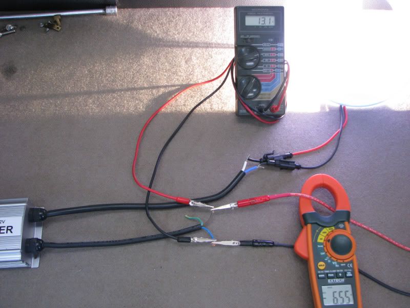
Red and black wires in lower right are coming from my 30 Volt/50 Amp variable power supply. One thing I did not show...The gray meter I'm using to measure Volts during the "power to the bulb" measurement does not measure as high as 25,000 to 35,000 KV so I have to keep one of the leads disconnected at the meter until after initial startup (2 seconds is fine). Orange inductive clamp meter is reading Amps.

In both pictures, Volts x's Amps = Watts.

Ballast Input Watts: 13.1 Volts x's 6.55 Amps = 85.8 Watts

WattstestingInput.jpg


Watts to the bulb: This ballast puts out AC power to the bulb so the Orange meter is switched to AC Amps. 121.8 Volts x's .56 Amps = 68.2 Watts.

WattsOutput.jpg


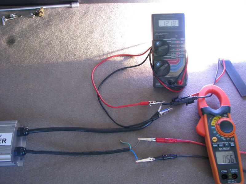
This ballast is multi-level output. At this setting, it is 79.5% efficient: 85.8 Watts x's 79.5% = 68.2 Watts
 
Last edited:

IgNITEor

Newly Enlightened
Joined
Oct 1, 2006
Messages
193
Location
central Oregon high desert
BVH!

I always get amp'd up using power in/power out metering.
My early Frankenstein ballast operates at a lousy 50% power factor,
but makes for a great heater during chilly lighting sessions. :D

Have you noticed any difference in readings if you swapped the meters around? Very nice demo.
 

incsulnum

Newly Enlightened
Joined
Oct 13, 2009
Messages
1
I'm not sure about how possible some of the things you mention would be, but there is one setting that may interest you, if you haven't seen it already
 

brickbat

Enlightened
Joined
Dec 25, 2003
Messages
890
Location
Indianapolis
Watts to the bulb: This ballast puts out AC power to the bulb so the Orange meter is switched to AC Amps. 121.8 Volts x's .56 Amps = 68.2 Watts.

You're OK with your method for measuring the DC input power to the ballast. But, on an AC circuit, V x A is not necessarily Watts. This would be the case in the simple case where both meters (volts and amps) were RMS reading, and the voltage and current waveforms were both sine waves and the load was linear and nonreactive.

But HID ballasts do not generally provide sine wave current waveforms and HID lamps are non linear loads. To get an accurate power input measurement to a HID lamp, you need a o'scope, to see the true voltage and current waveforms. Then, they can be instantaneously multiplied and you'll get true power.

So, while your end results seem reasonable, keep in mind there are some errors looming...
 

IgNITEor

Newly Enlightened
Joined
Oct 1, 2006
Messages
193
Location
central Oregon high desert
This would be the case in the simple case where both meters (volts and amps) were RMS reading, and the voltage and current waveforms were both sine waves and the load was linear and nonreactive.

You're describing a AC source supplying a AC resistive load, is that right?

Therefore, if BVH were to use true RMS metering and he knew the power factor of his power supply with this load applied, couldn't he measure the input amps on the line side of his power supply and the lamp current and get a closer reading of what the ballast/lamp efficiency is?
Since his ballast output is square wave, I understand this will not register well with the current measurement in the lamp circuit.
I'd like to see a DC current measurement on both ends of the ballast and see how the lamp current displays.

BVH, brickbat has corrected me before and I'm trying to keep foot out of mouth here.
I wish I had one of those ballasts in my arsenal to work with.Your demo is intriguing and we're obviously not done here. Keep the gear handy :wave:!
 

BVH

Flashaholic
Joined
Sep 25, 2004
Messages
7,023
Location
CentCalCoast
I'm fairly knowledgeable in "electrics" but don't have a technical background in "electronics". I wish I did. But I can certainly follow directions and if I have the right equipment, can make the measurements needed. But in any case, are not the measurements I have made here in this thread, fairly close? Up to what percentage could they be off? 5 to 10%? And if we're dealing with DC input and DC to the bulb, are my methods sound and accurate?

I've used O' Scopes in the automotive field so I understand their use. I don't have one for this type of work but could obtain one if they are reasonably priced. I understand PWM, and somewhat the term, waveforms.
 

IgNITEor

Newly Enlightened
Joined
Oct 1, 2006
Messages
193
Location
central Oregon high desert
BVH, your readings are just dandy and close enough to demonstrate basic losses. I, too, wish for a nice o'scope. Maybe under the Christmas tree sometime this decade.:whistle:
But for now, I make do with two Fluke meters. One very old 87 and a 322 model. The 87 is a true RMS meter and does the trick on accurate AC measurements. When the 87 & 322 (clamp meter) trade places, there is often a difference in readings, depending on what the load is.
It's interesting what your clamp meter reads in the lamp output. Being square wave (funky DC) I didn't realize it would read in AC mode. Shazam!!

When I did my first test runs of the Frankenstein ballast, I almost forgot to remove the 87 from the lamp circuit prior to ignition. Close call.
Even as it sat 4-5 feet away, the RF generated by the spark gap and coil made the display hallucinate.
If you can, it would be great to see another test of your metering to back up your first reading. That would be to measure DC amps in and out of the ballast to see if the loss shows in that method as well.

Does your ballast get warm after awhile?
 

brickbat

Enlightened
Joined
Dec 25, 2003
Messages
890
Location
Indianapolis
You're describing a AC source supplying a AC resistive load, is that right?

Yes - Sine Wave AC source and resistive load.

Therefore, if BVH were to use true RMS metering and he knew the power factor of his power supply with this load applied, couldn't he measure the input amps on the line side of his power supply and the lamp current and get a closer reading of what the ballast/lamp efficiency is?

I don't think so. We can measure the DC input to the ballast accurately. The problem is measuring the output power to the lamp.

BVH - As I noted, I think your method of measuring the DC input to the ballast is good - you apparently have a clamp-on DC ammeter, which is a nice thing. Maybe not as accurate as a conventional DC ammeter, so you might check that. But otherwise there are no twists - in a DC circuit Watts = Volts x Amps. Always.

Measuring the actual power delivered to a HID lamp is not an easy task. Your method is a reasonable way to start out, but its accuracy depends on the shape of the voltage and current waveforms, which are unknown. So, I wouldn't want to guess at its accuracy. As I'm sure you know, HID ballasts are essentially switch mode power supplies, and 80% is a pretty 'typical' efficiency number. So, in the case you described above, I think your method is yielding accurate results. (but that's a guess/opinion - not based in fact)

Making an accurate measurement requires a scope, and also 3 more details. You need a good voltage probe capable of reading the lamp voltage, which may not be ground referenced - so it might need to be a differential measurement. You need a current probe capable of decent high frequency response - probably to 1 MHz or so. And, its nice if your scope is digital, so it can do the point-by-point multiplication for you. Otherwise you'll need to somehow capture the sample file, and import it to a PC to do the math on it.

As I said, not easy...
 

IgNITEor

Newly Enlightened
Joined
Oct 1, 2006
Messages
193
Location
central Oregon high desert
Oh gosh darn it :shakehead why can't electricity flow when & how we want it to under challenging circumstances.

While I dig around for a certain textbook I worship, BVH, can you rig your demo to measure DC amps using either of your meters, whichever one has the 10 Amp inline DC input, to measure the load (somewhat) of your lamp? You'll have to jumper across the probes until the lamp strikes, of course.
We already know what the ballast is drawing under load.
We also know what the lamp's load is in the AC mode, sort of.

I recall you're using a 55 watt HID or is this the famous overdriven 35 Watt version with the ballast set for the higher output? :naughty:

I was getting my head around brickbat's explanation of sine & square wave's awkward relationship when I thought about your ballast getting
plenty toasty. It's becoming clear that you're operating at much less efficiency than your original readings have suggested.
Since we've moved, all of my brain pages are in boxes out in the garage!
I was going to look into "known values" applied to switch-mode power output to see if we can work with what we know about the output in the lamp circuit so far, especially if we can another voltage measurement.
For this we'll need DC Volts after the lamp strikes, again using a jumper across the probes during ignition.
Last step is to get the output frequency(s) from the mfr. if they're willing to part with that info. We may have better luck with a savvy stateside
dealer who has access to design specs.

Dear Santa:

http://us.fluke.com/usen/Products/Fluke+190.htm
 

IgNITEor

Newly Enlightened
Joined
Oct 1, 2006
Messages
193
Location
central Oregon high desert
For this we'll need DC Volts after the lamp strikes, again using a jumper across the probes during ignition.

:caution: ALERT! :poof: Don't listen to this guy! He's suggesting to risk damaging your meter.

I'm concerned some of the ignition voltage at it's high frequency may work around the jumper. Hope it's not too late, but you probably already avoided that.
 

BVH

Flashaholic
Joined
Sep 25, 2004
Messages
7,023
Location
CentCalCoast
I never (never say never, see below) connect the Voltmeter until well after the initial 20+KV strike. I usually have the + lead connected and make the final - lead maybe 10 seconds into the starting cycle. Once in a while I forget and the lamp will fail to strike and there is a noise in my meter (the 25 year-old+ Radio Shack meter) like a safety relay going off. It, so far, has not done any damage that I can see. I haven't done anything yet but I can remember from when I have, in the past, had the induction meter set to DC instead of AC for Amps on an AC system and the reading is something like "1" or less than "1" when I know it should be 5 or more. It's been my reminder to turn it to AC.
 
Top