wquiles
Flashaholic
This is my first time modding this Barbo host, as I previously have been modding the Bomb-proof host for a couple of forum members (see my signature for links to other Barbo projects).
It has taken me a LONG time to put this one together, because I was trying to make a regulated version for this host, and the ideal driver (hipCC) fits fine in the larger diameter of the Bomb-proof hosts, but not on the smaller diameter of this U9 host. I did a lot of "experiments" along the way to try different things, so here is a pictorial of the project.
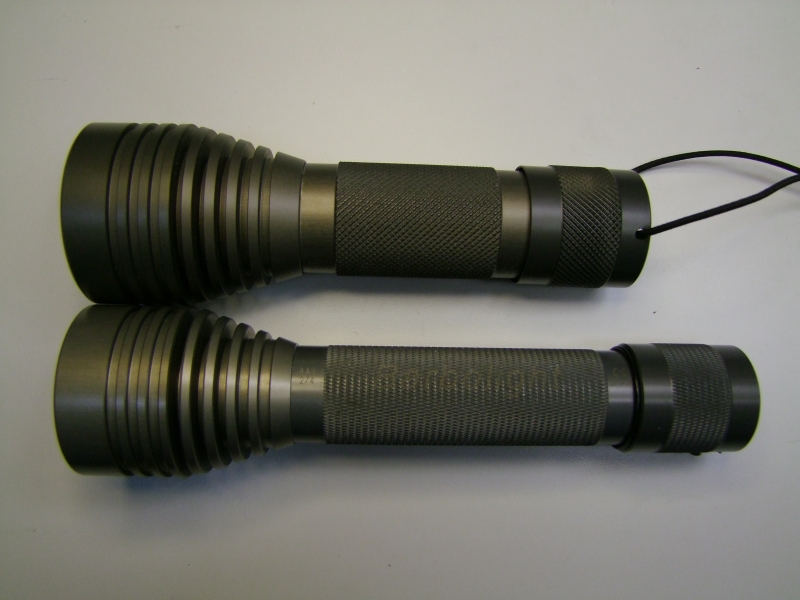
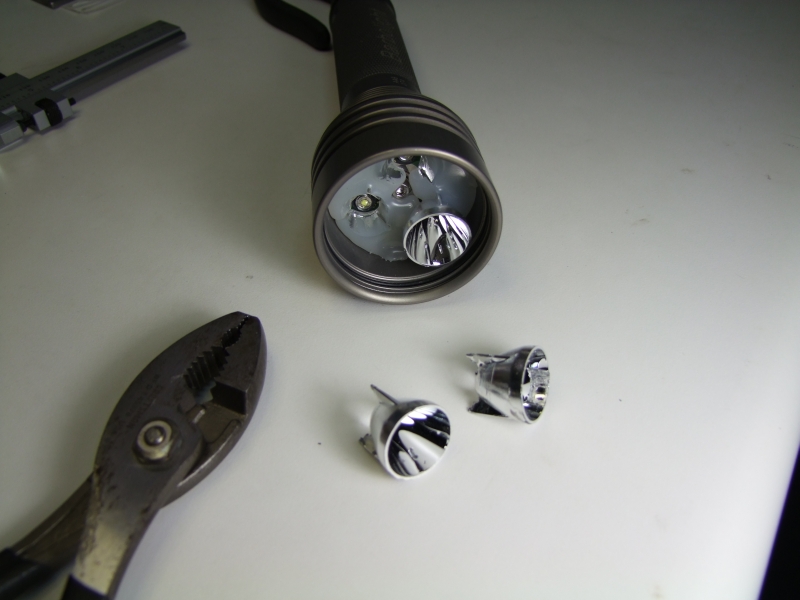
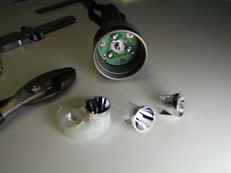
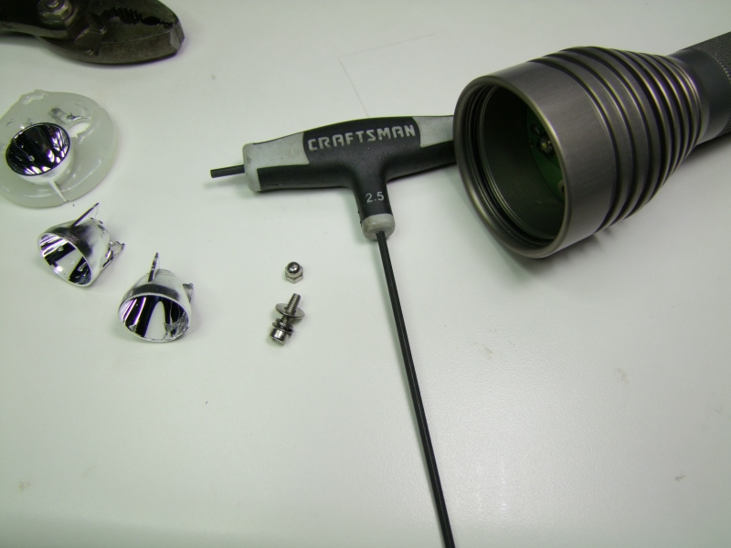
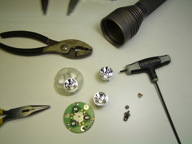
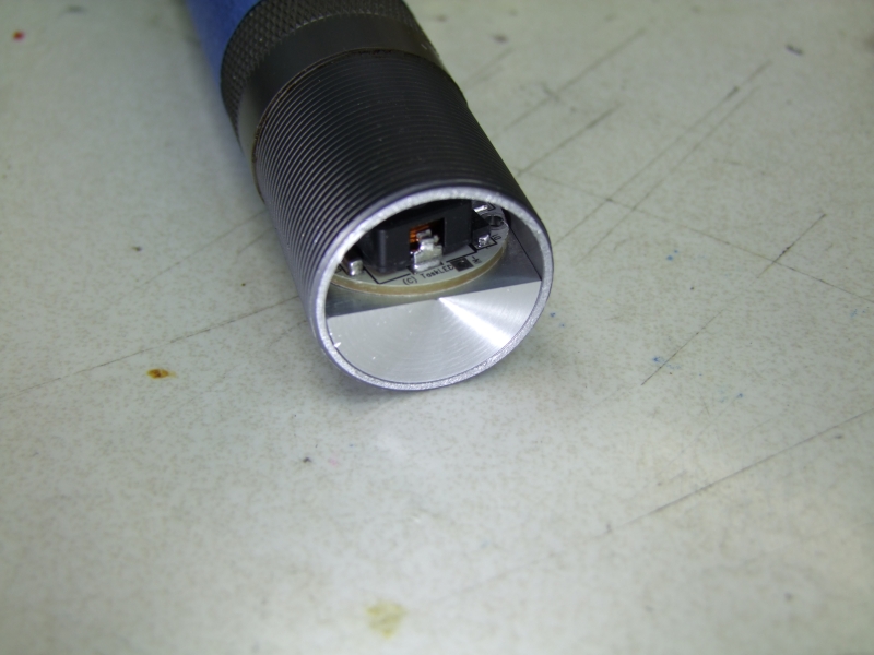
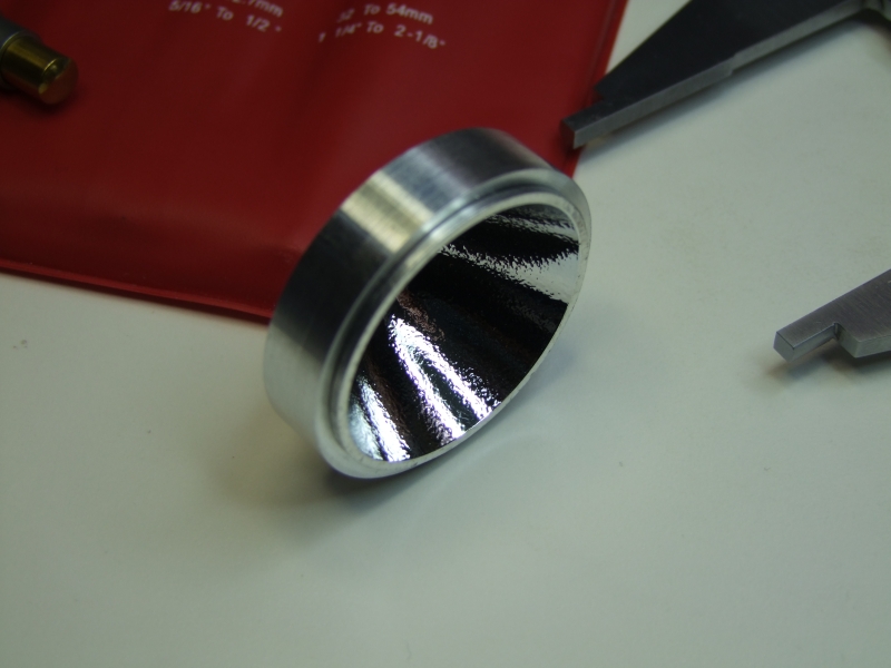
FIrst, I had to get the original U9 host in pieces. Lens was already removed prior to the light arriving to me, but the Barbolight does a good job in making these hosts nearly indestructible, so it was still laborious to get everything separated:
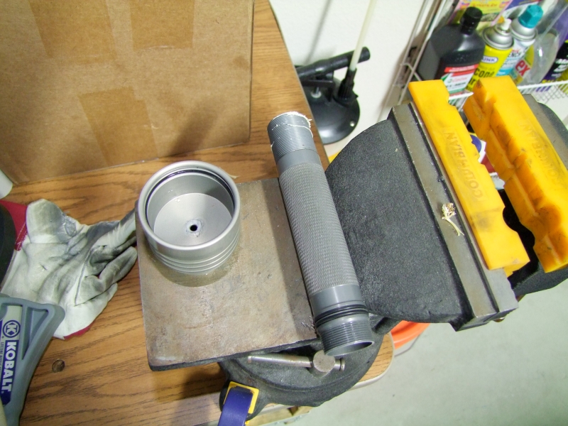
I then had to heat the body/head in my Powder Coating oven to 450F, so that the factory epoxy would soften enough for me to unscrew the head off:
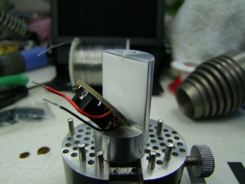
Since I wanted to use the hipCC (about 1.1" dia) and this host was about 1.0" dia, I would have to come up with a custom heatsink. After discussing this a little with George (from www.taskled.com, designer of these drivers) I proceeded to lightly sand two sides of the hipCC to make it fit on the host, but sideways. :
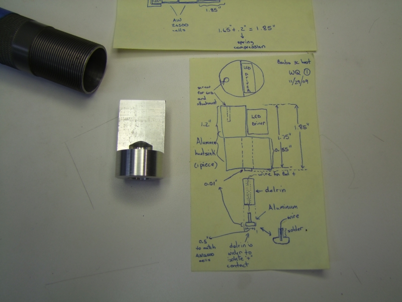
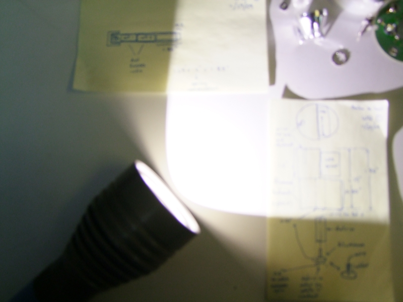
You can see here in my hand written notes my original design:
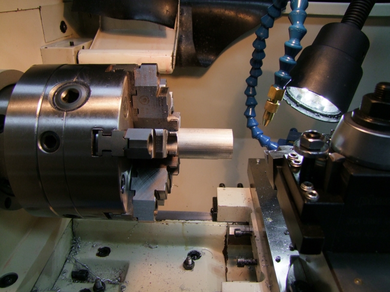
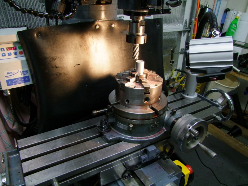
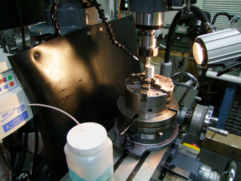
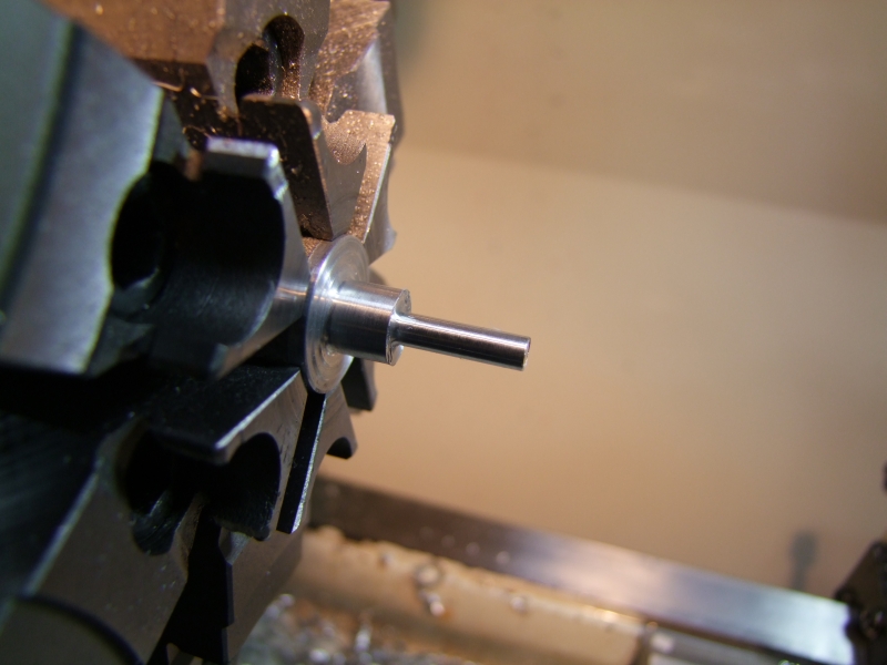
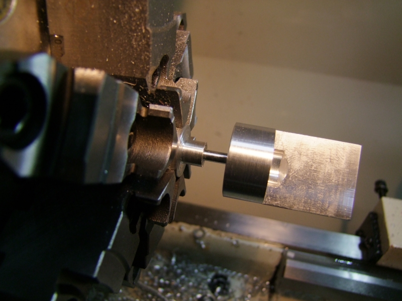
I then continue work on the mill:
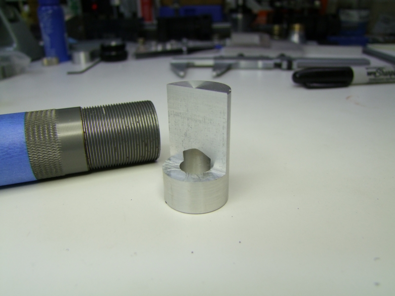
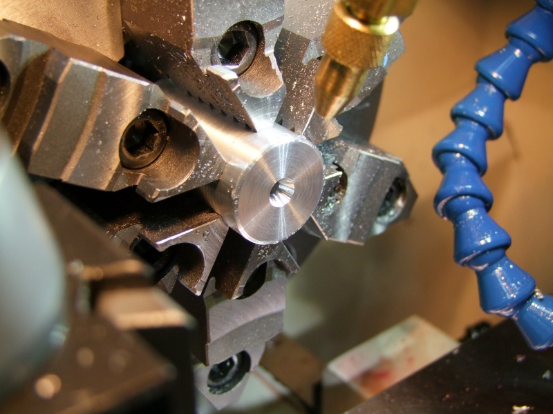
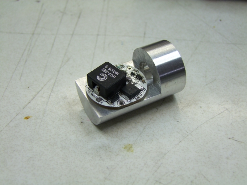
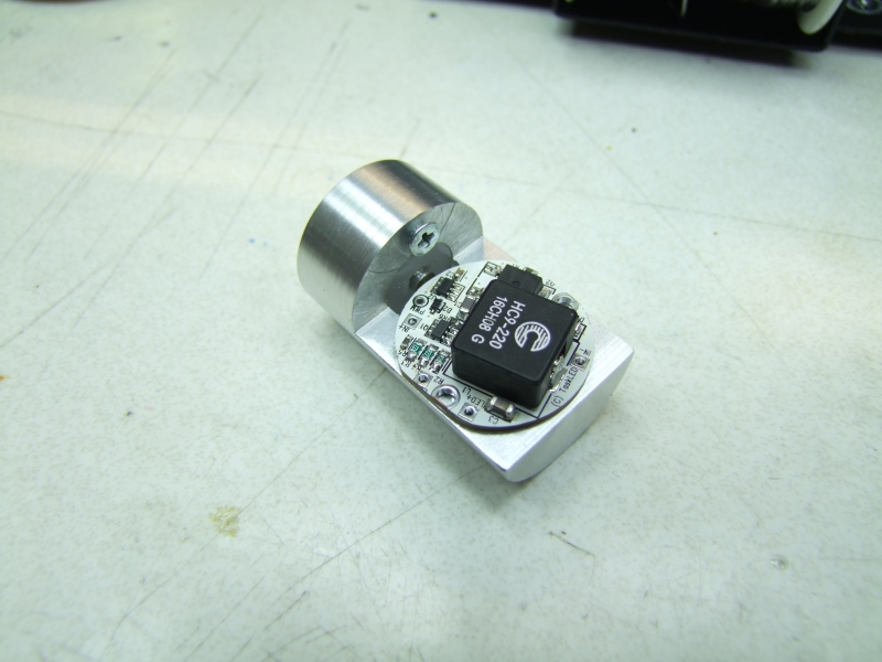
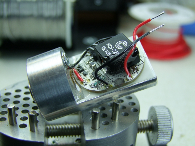
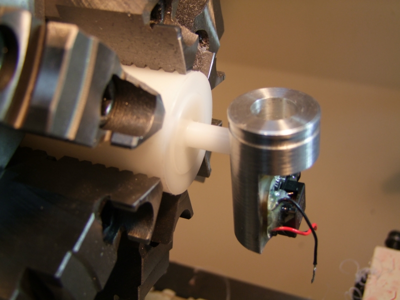
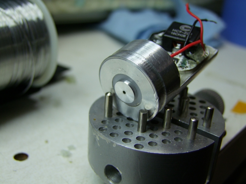
And for the first time I was able to test the fit of the hipCC on the new custom heatsink:
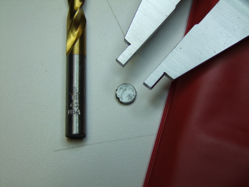
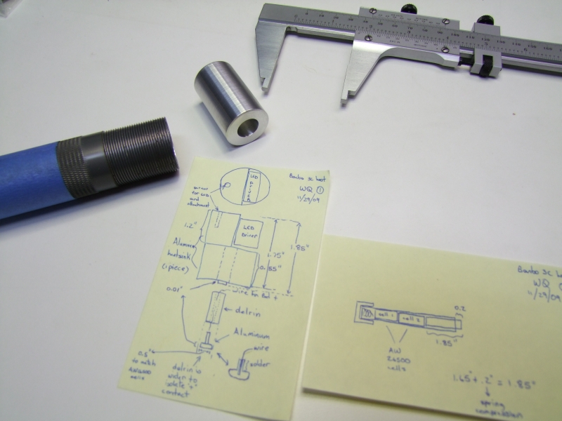
Here is a close-up of the heatsink next to the original paper design:
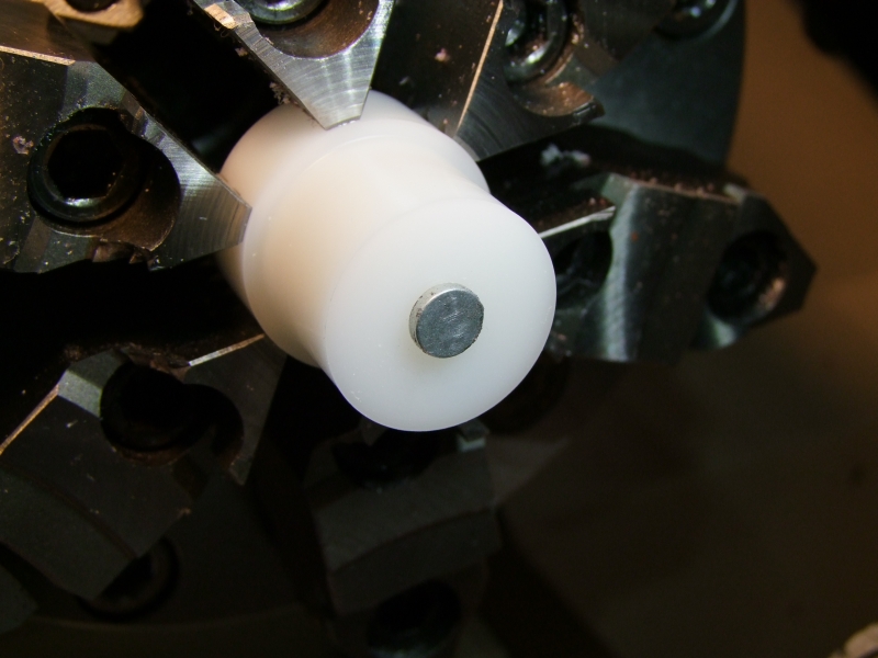
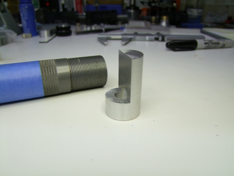
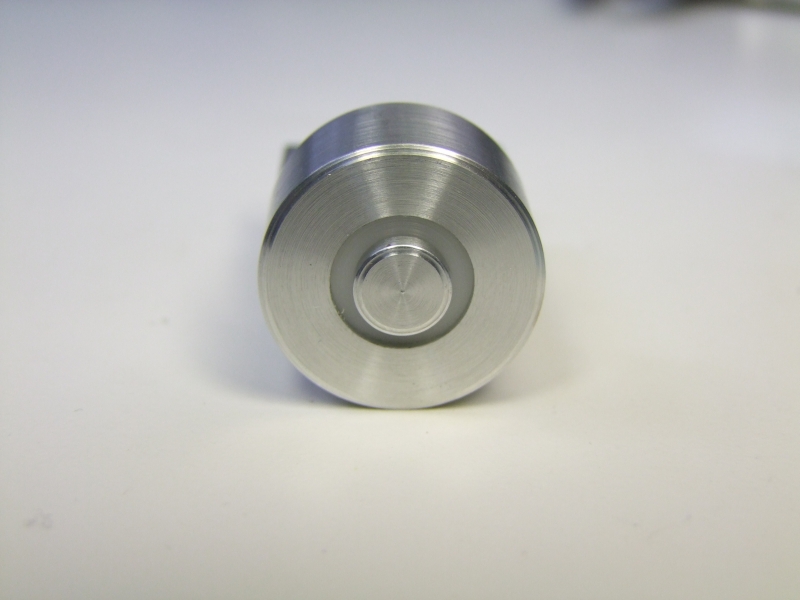
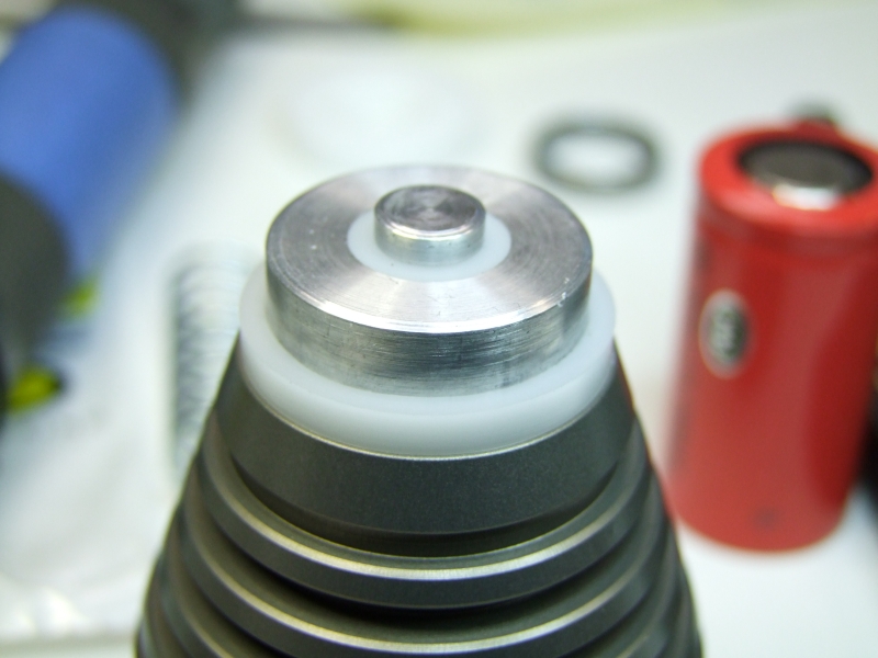
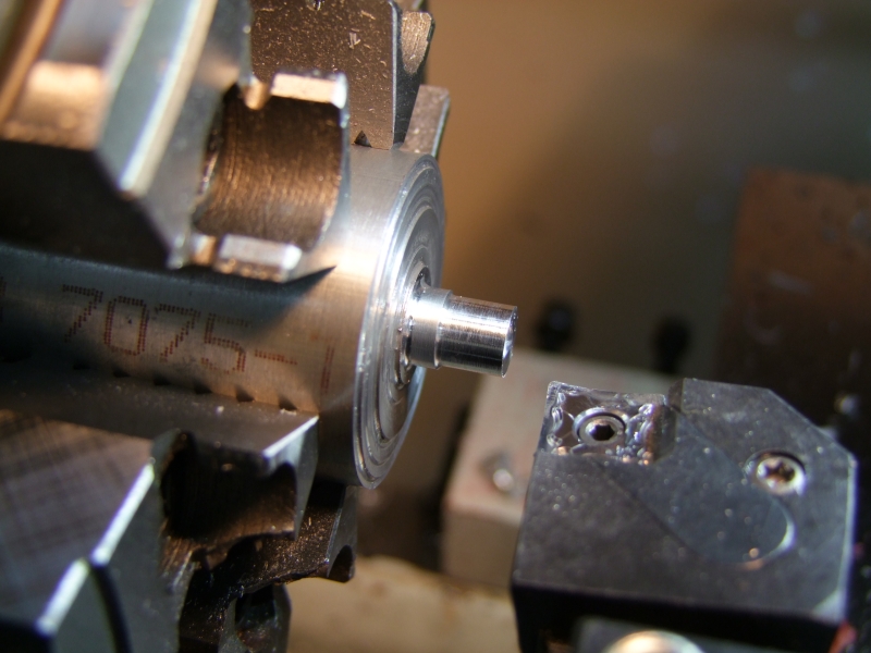
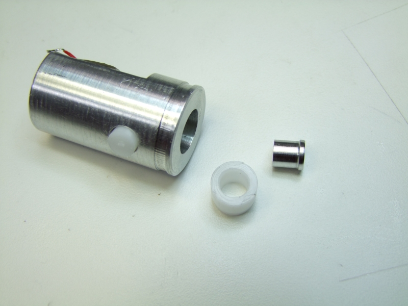
I continued to make progress on the inner part of the heatsink, which would be composed of a Delrin sleve, with an Al center piece to carry the "+" from the battery to the driver:
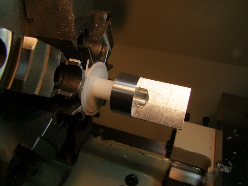
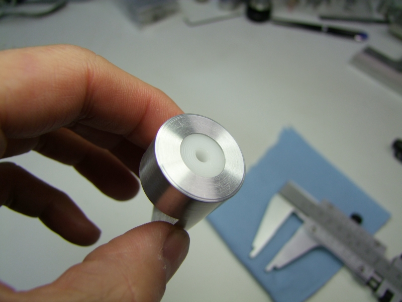
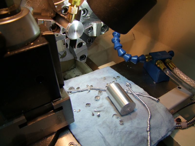
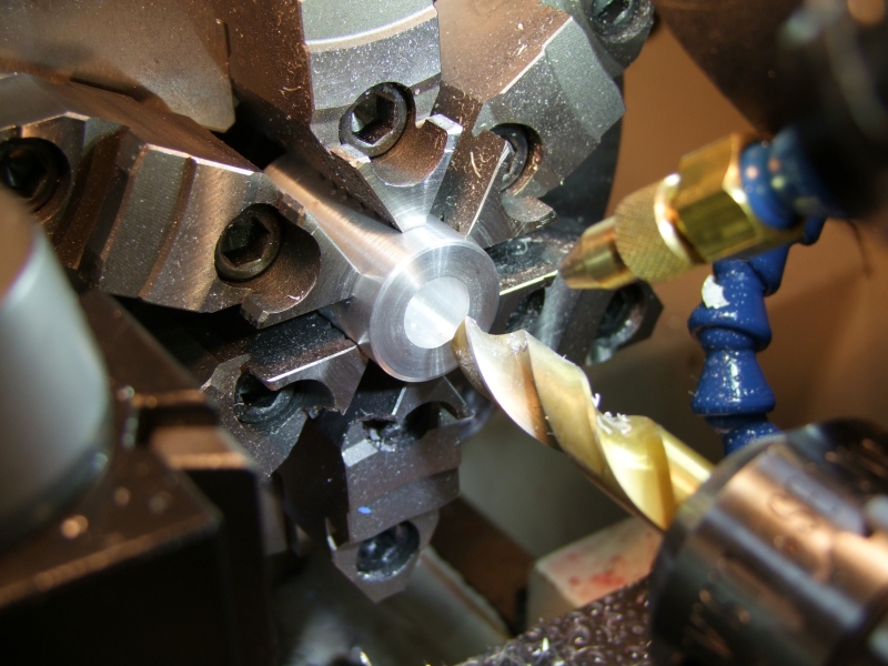
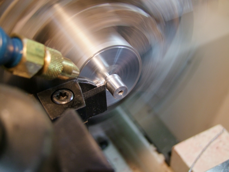
Here I am working on the inner Al piece:
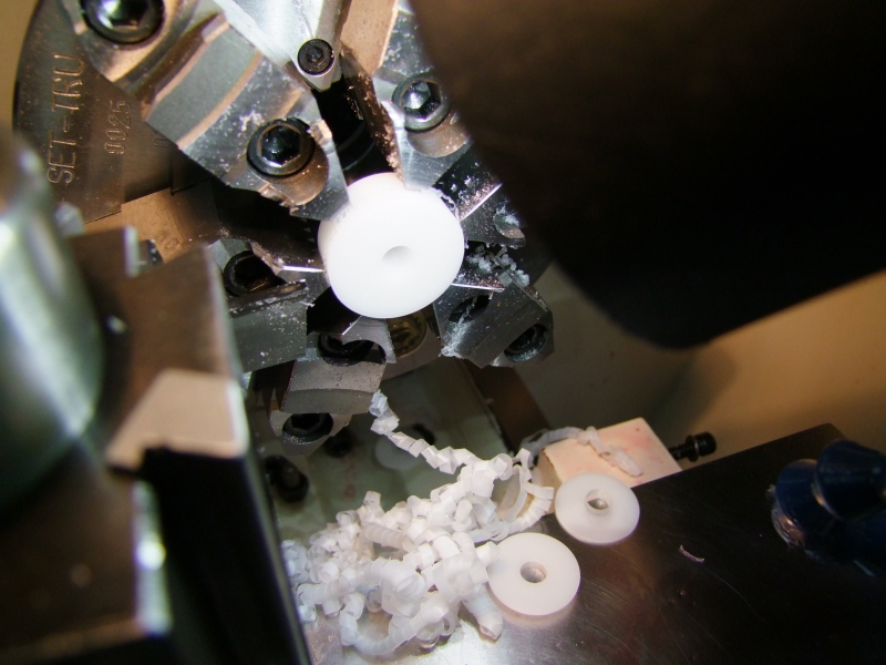
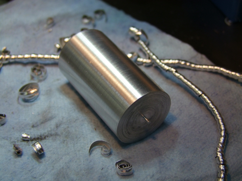
The pieces:
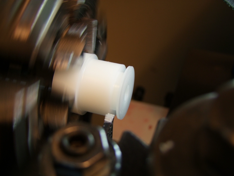
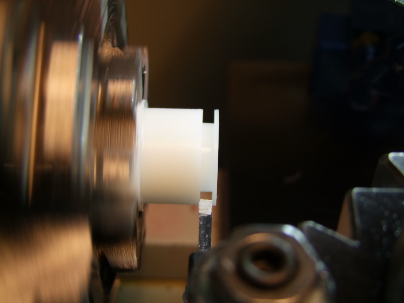
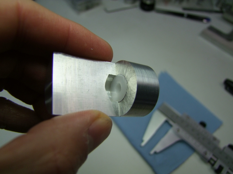
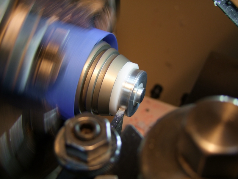
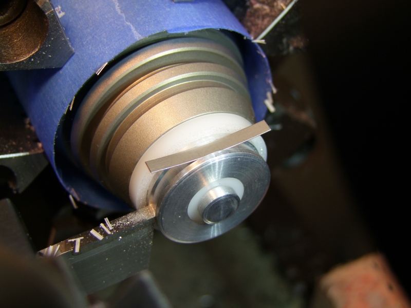
Making a small groove to wire/solder the wire that will be going to the driver:
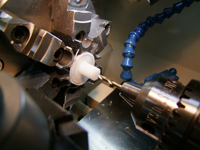
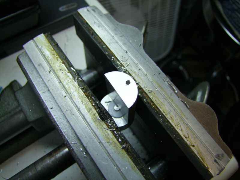
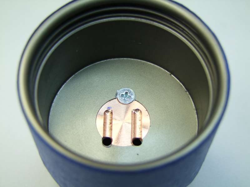
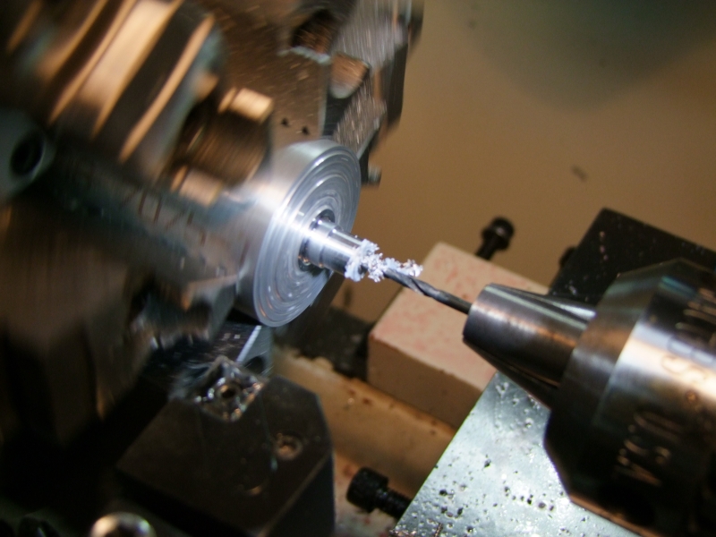
I then drill and tapped the location for the screw that will carry the Bat "-" to the driver:

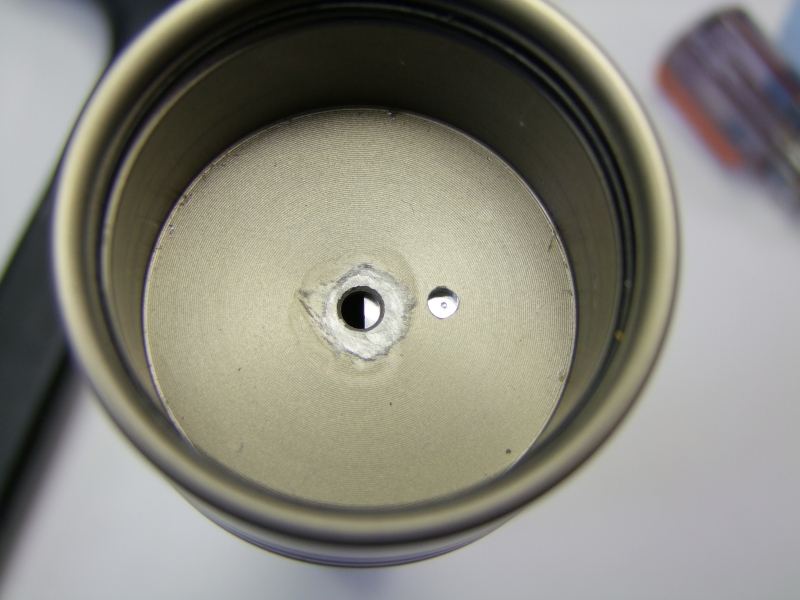
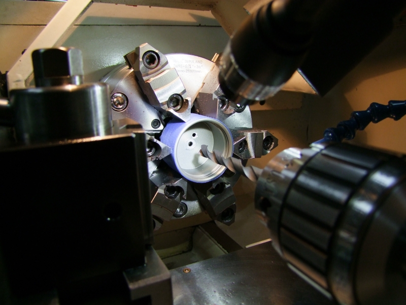
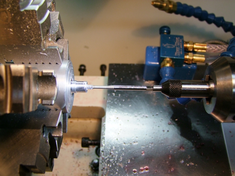
I then drill a hole in the head that will mechanically keep the heatsink in position:
and then used the head to transfer punch that location to the heatsink:
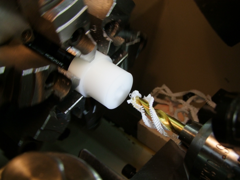
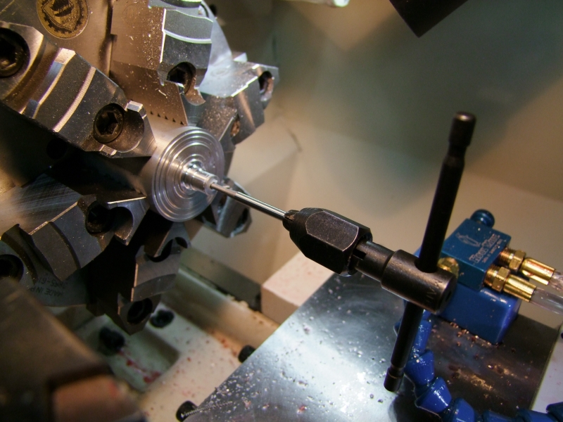
I then drill and tapped that hole in the heatsink:
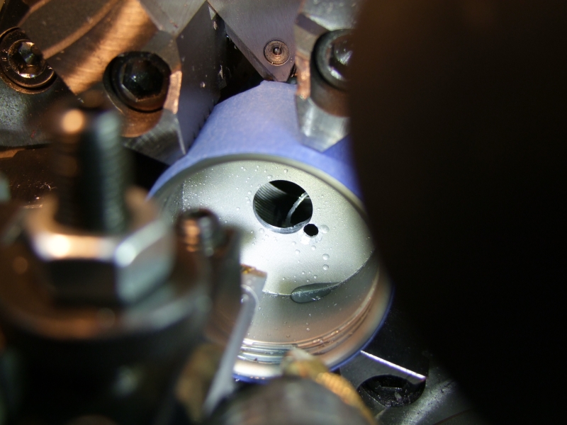
then counterbore the hole to make sure the screw head would be flush with the head (to prevent it from contacting the reflector later on):
Having done this one project, I would not do it again this way, but I decided to install a copper disk for the LED:
I left a thin self to help keep the press-fit copper heatsink in place:
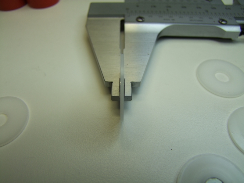
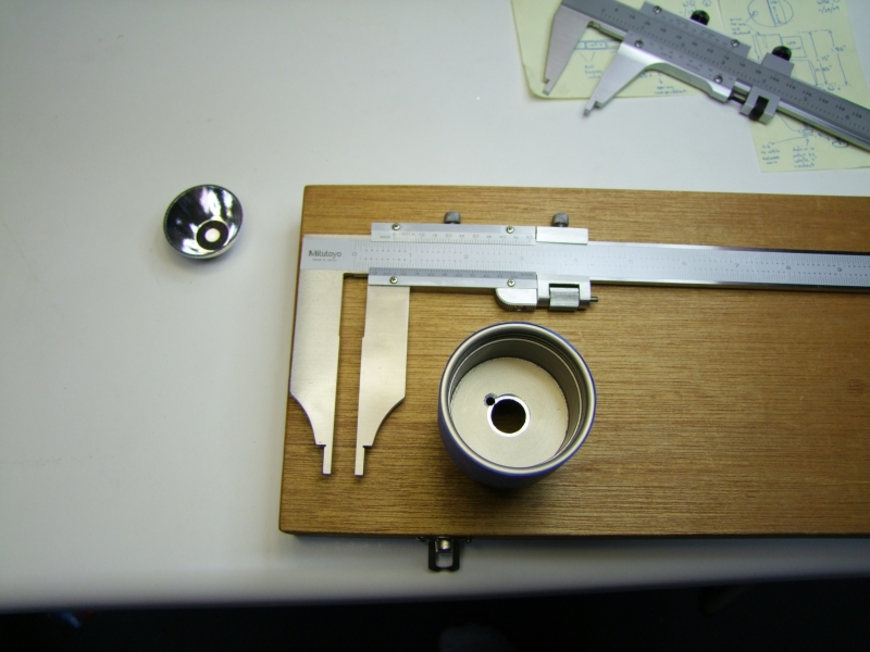
I used my long jaw calipers (thanks Barry!) to measure the hole:
and then make a custom thin heatsink from C110 copper:
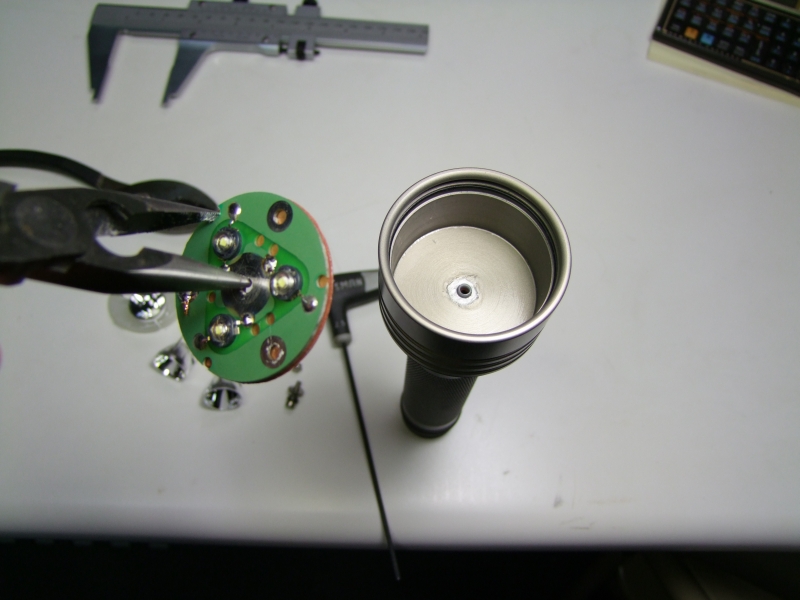
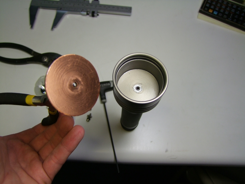
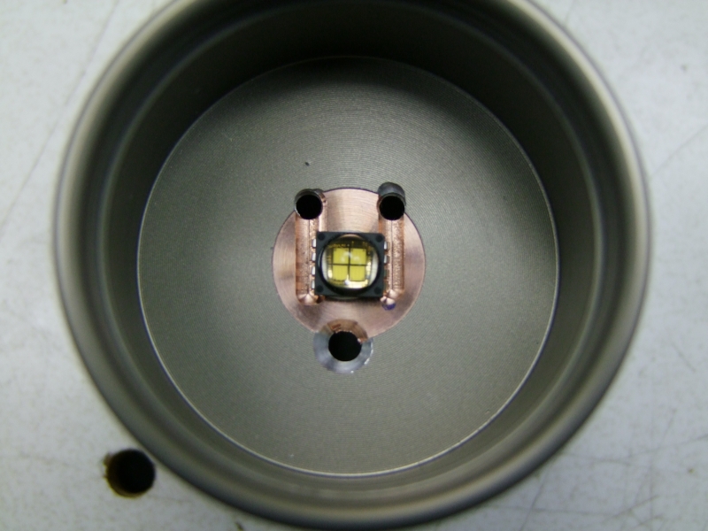
And here is how it looks once in place once epoxied in place:
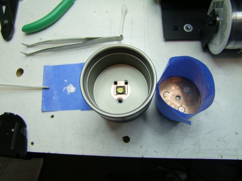
Here I am trying the MC-E to line up where I will be doing the milling cuts:
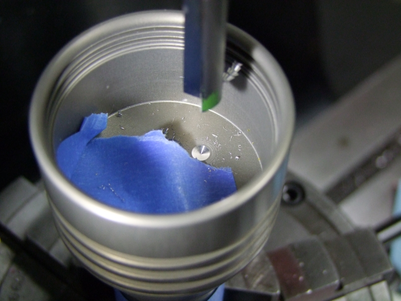
Doing the actual milling cuts (these allow me to position the wires even lower than normal so that they would be even less chance of a short circuit with the metal reflector - I don't want to leave anything to chance):
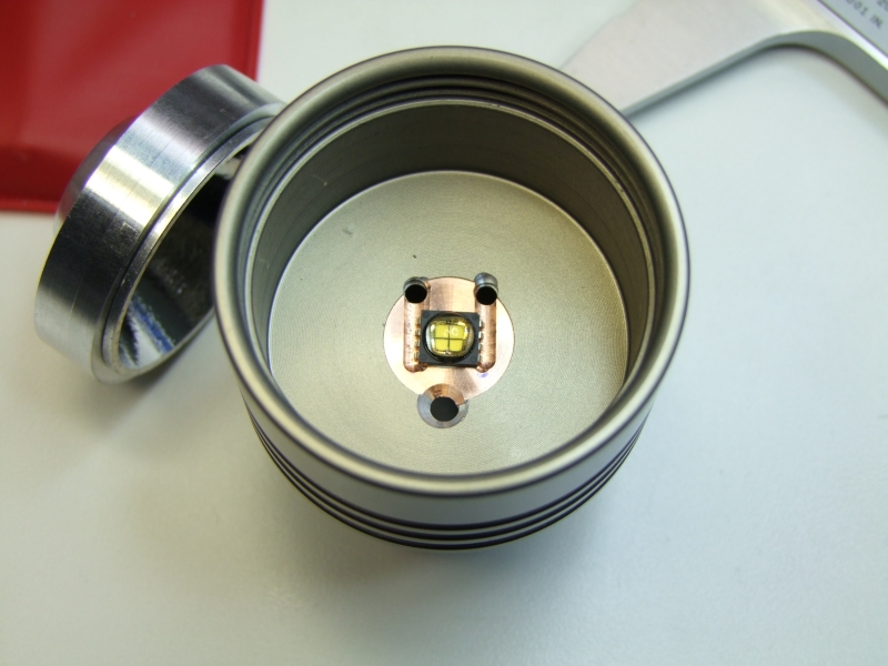
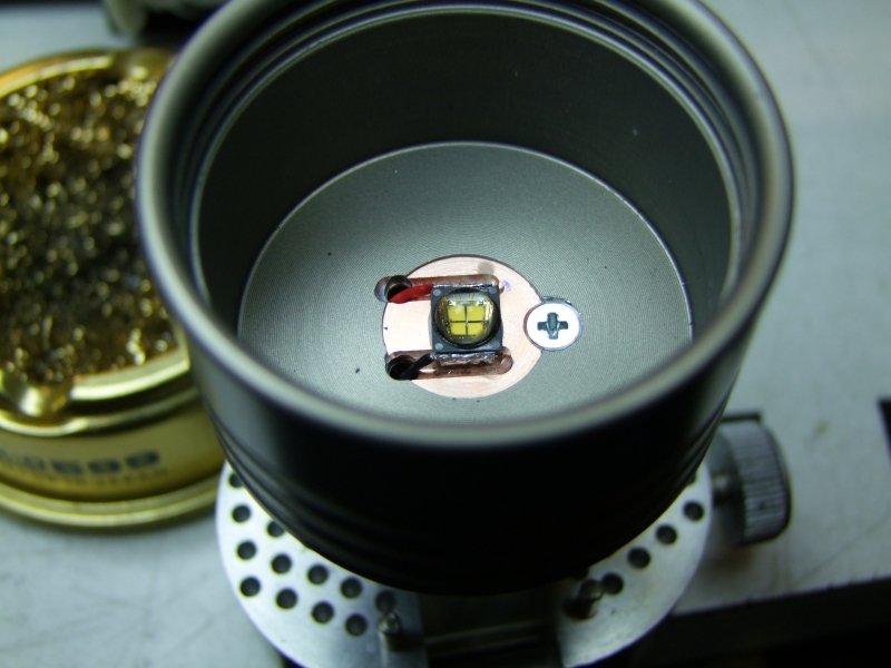
I used the Barbo copper heatsink (which is perfectly centered in the head as a guide to center and epoxy the emiter to the head:
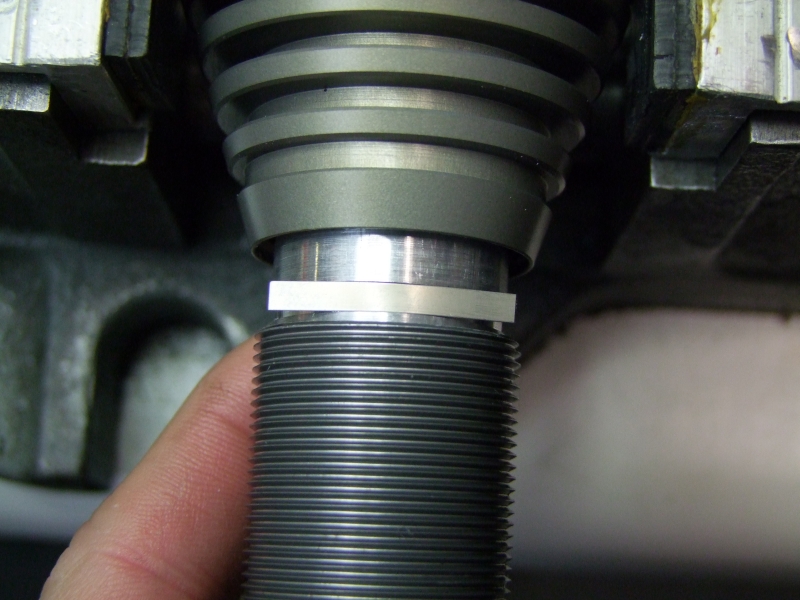
The reflector is perfect in terms of height, but not diameter-wise, so I need a centering ring:
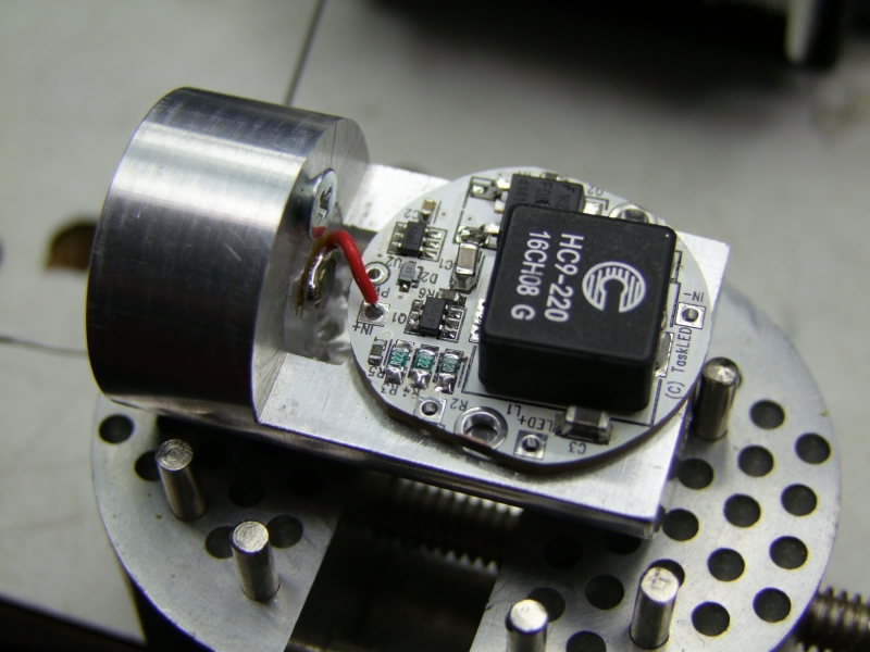
This was my initial attempt at securing the Bat + to the wire going to the driver. It did not work as good as I hoped, so I did it again (see further below):
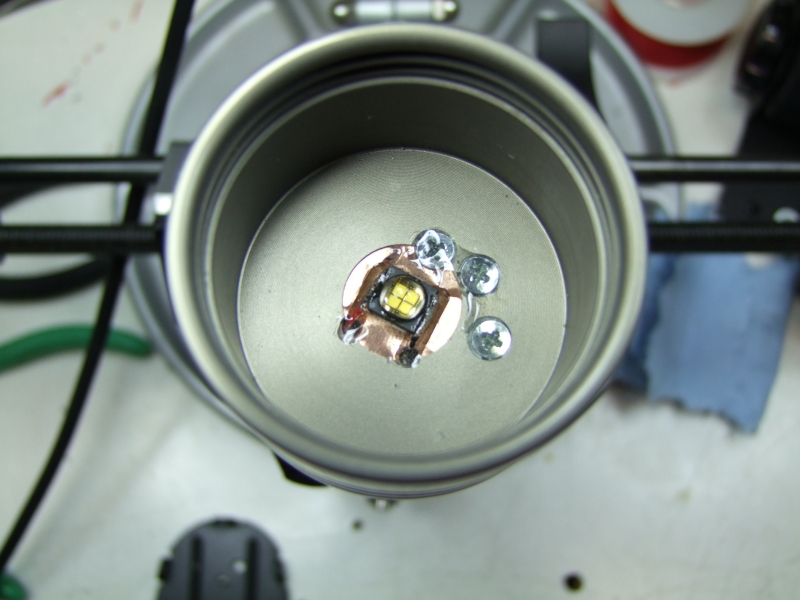
I wired the rest of the wires:
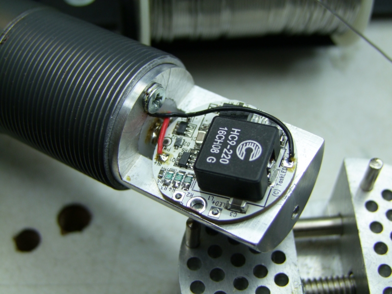
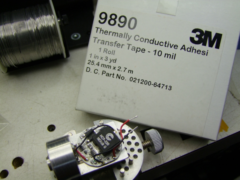
Then used thermal tape to provide a thermal path for the driver:
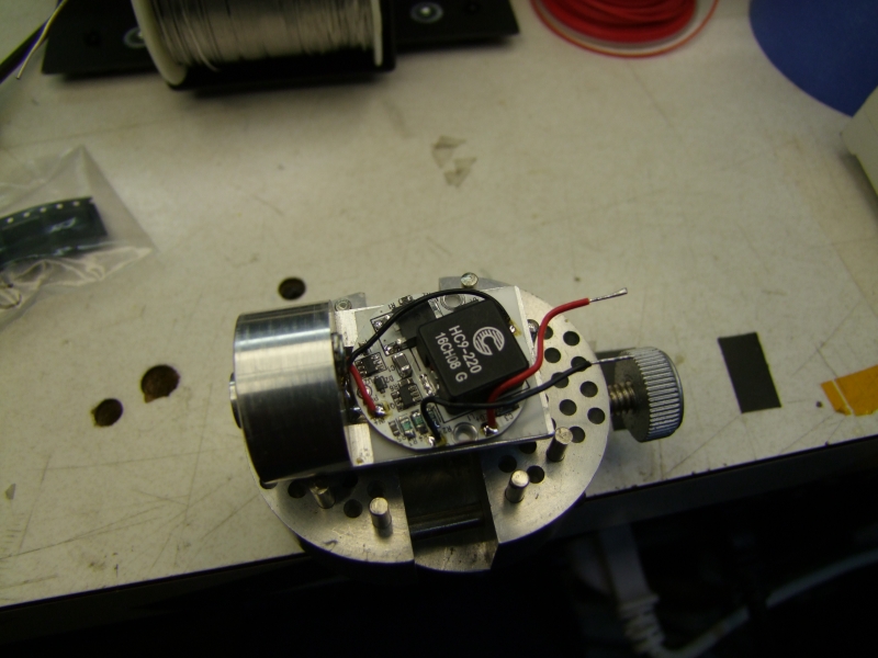
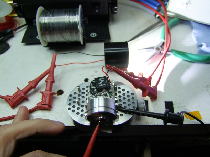
And then I tested the driver (LED being an SST-50 emiter):
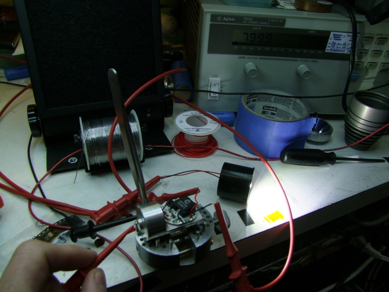
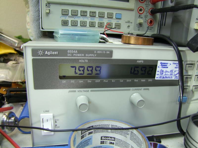
Input voltage/current:
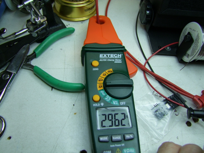
Output current going to the LED:
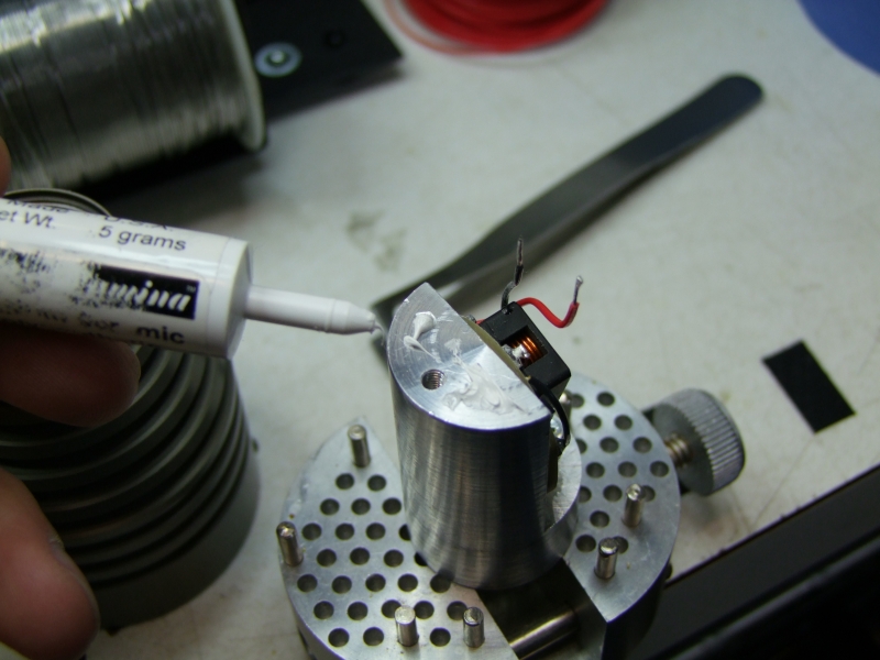
I used epoxy to keep everything in place:
and then tried on the actual head/host:
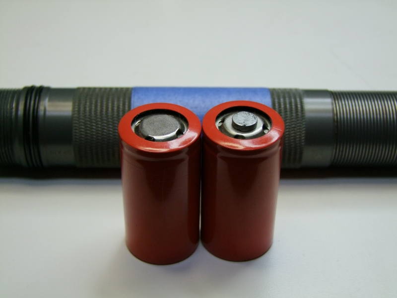
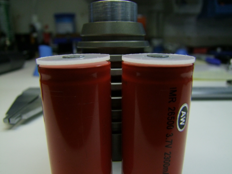
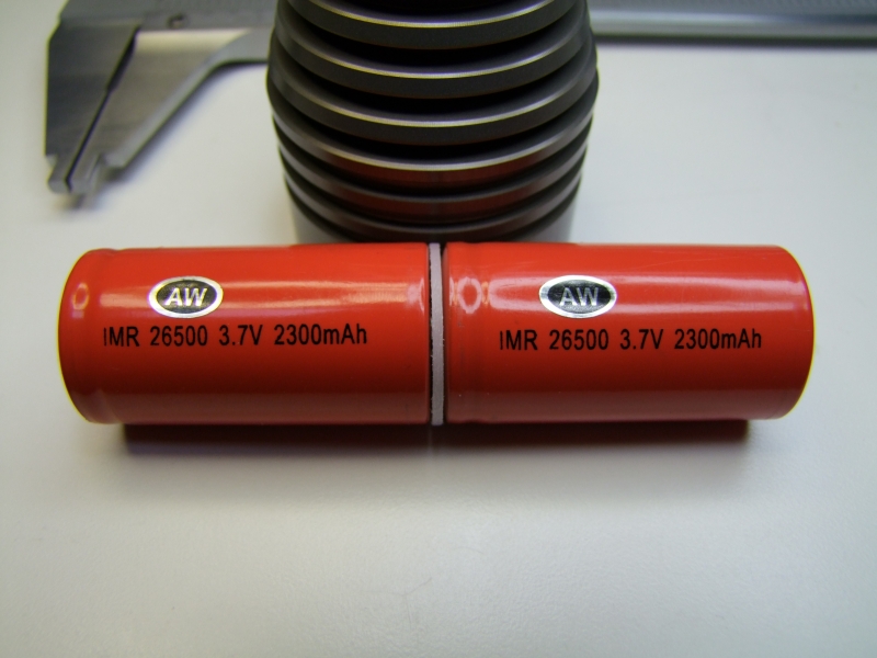
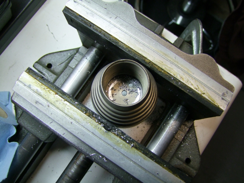
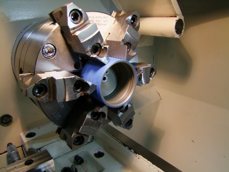
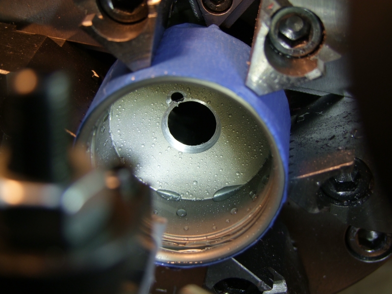
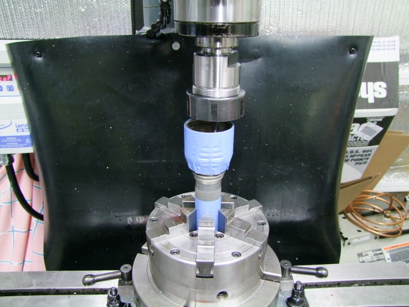
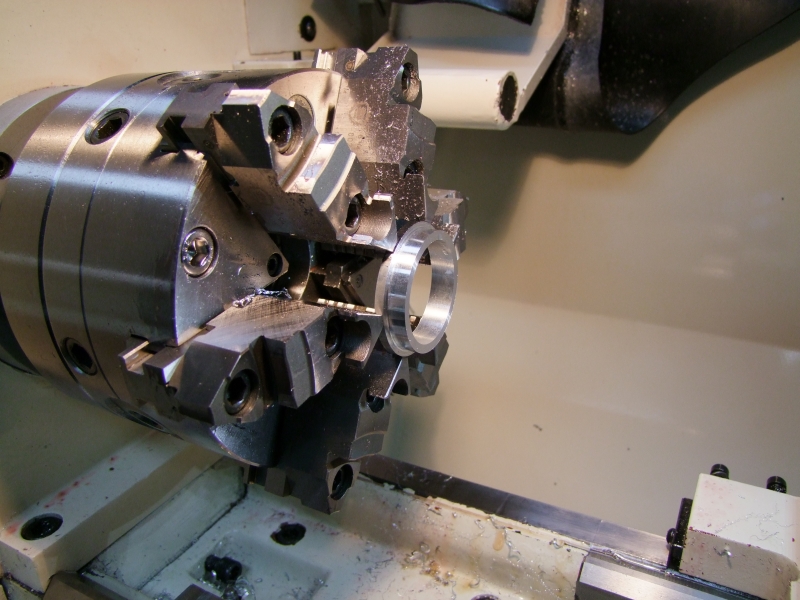
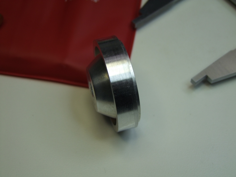
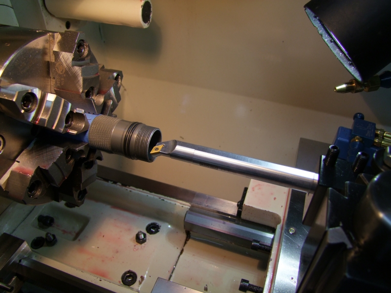
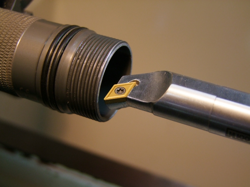
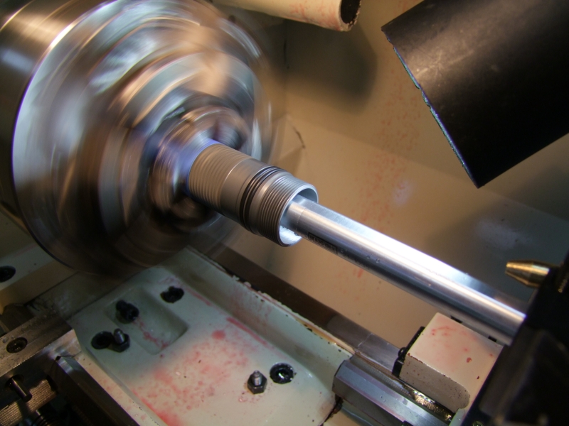
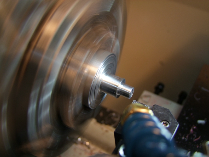
The AW 26500 cells that the owner wanted to use were a tad larger in DIA than the host (this being a "C" size host), so I bored it out slightly:
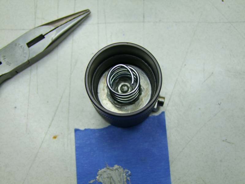
I was having some intermitent behavior (more on this shortly), so I added a flat spring to the heatsink body to aid with the Bat "-" connection to the heatsink. I first made a press-fit Delrin collar to keep the heatsink in place safely:
and then cut a groove for the flat spring (yup, the discarded negative contact from a Mag host - how is that for recycling!):
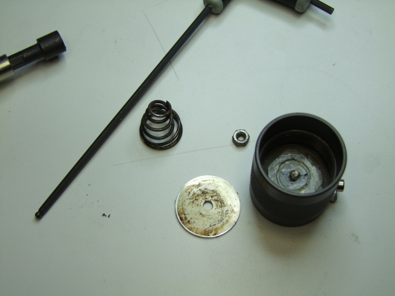
I also cleaned up the tailcap:
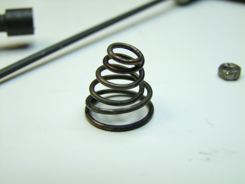
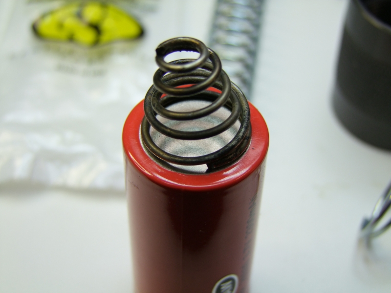
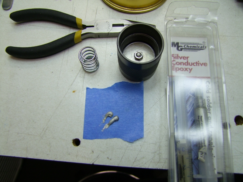
I decided I needed a better spring solution as it was not a great match for these cells. I used silver conductive epoxy to attach it to the tailcap:
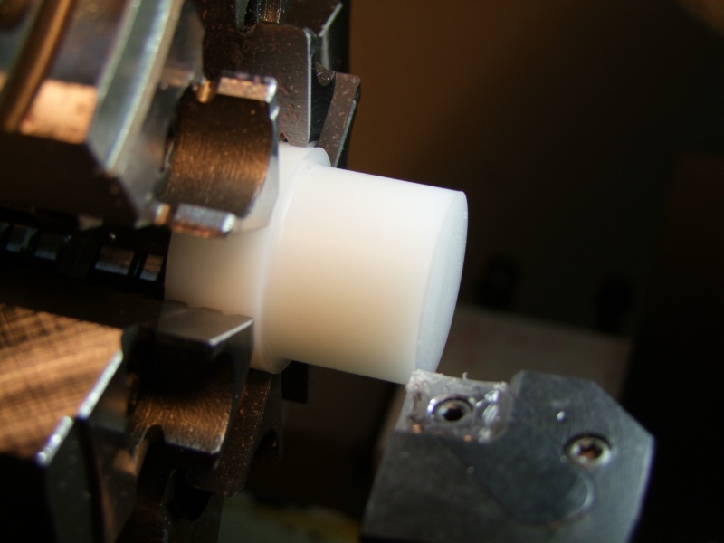
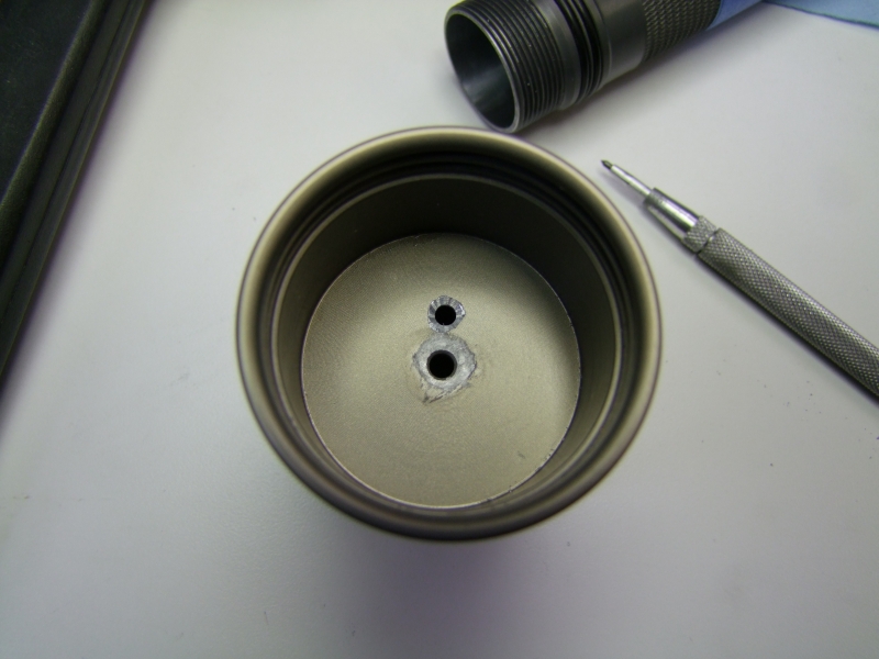
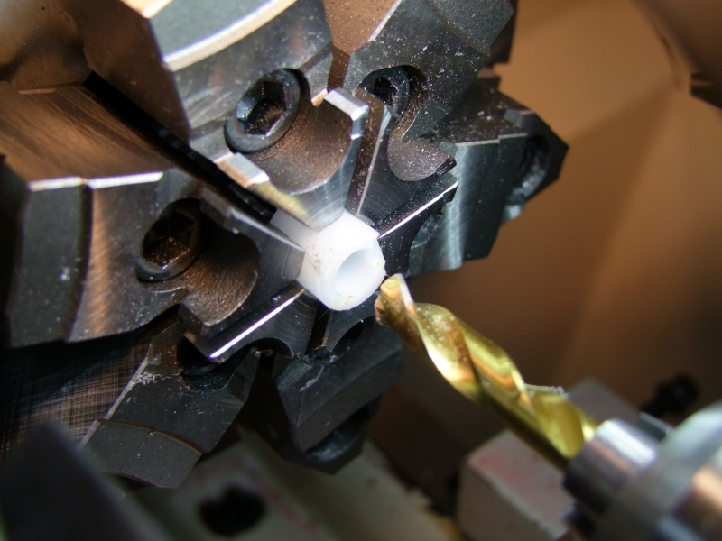
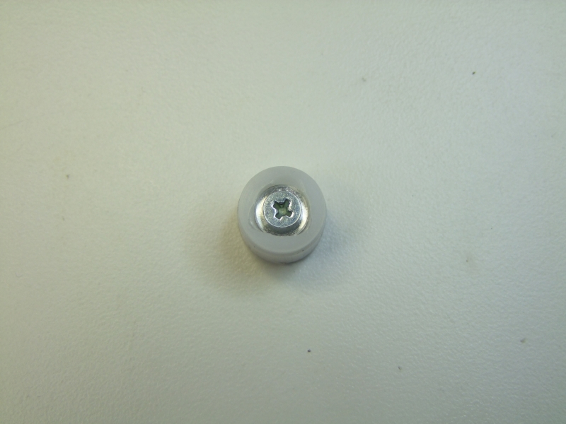
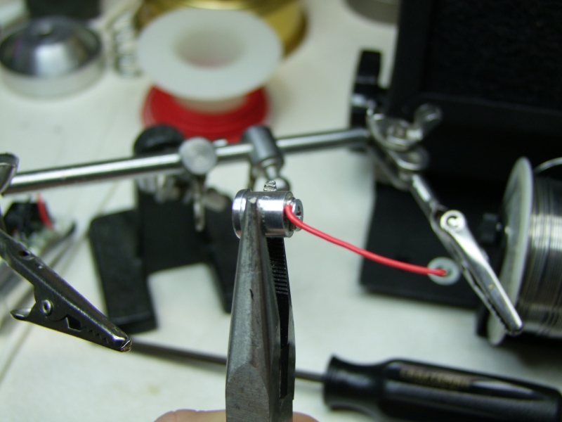
As I still had the same intermitent contact, I decided to re-do the Bat "+" contact by using a small screw instead, so that meant re-doing that section of the heatsink. Here I am enlarging the hole in the Delrin sleeve to allow for a larger Al center piece :
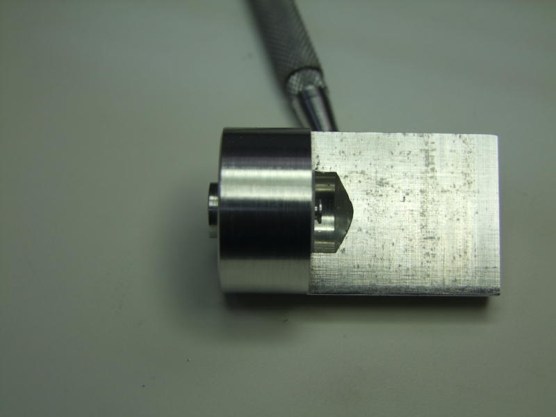
Here I drilled a side hole and made a small delrin plug to limit the travel of the new Pos plug:
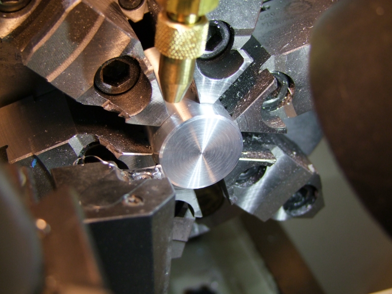
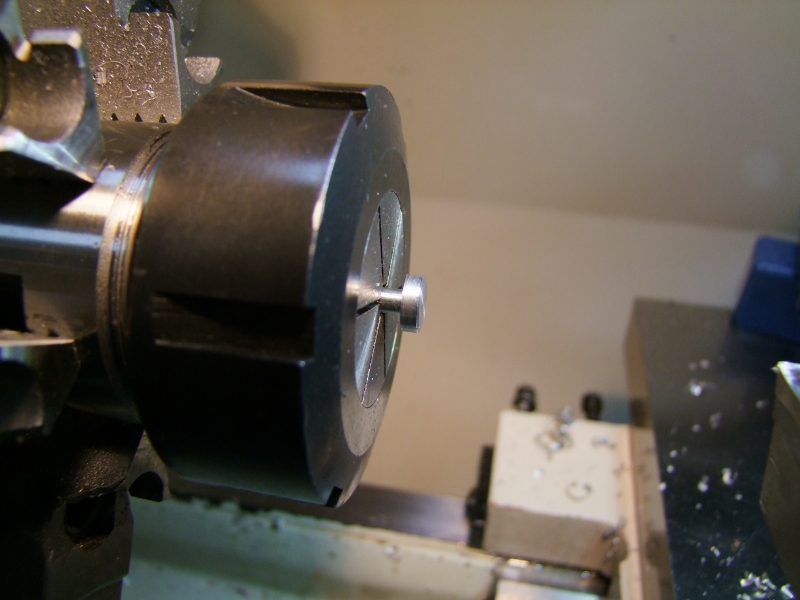
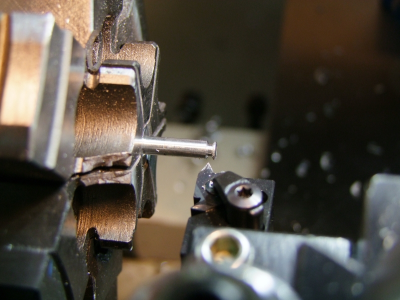
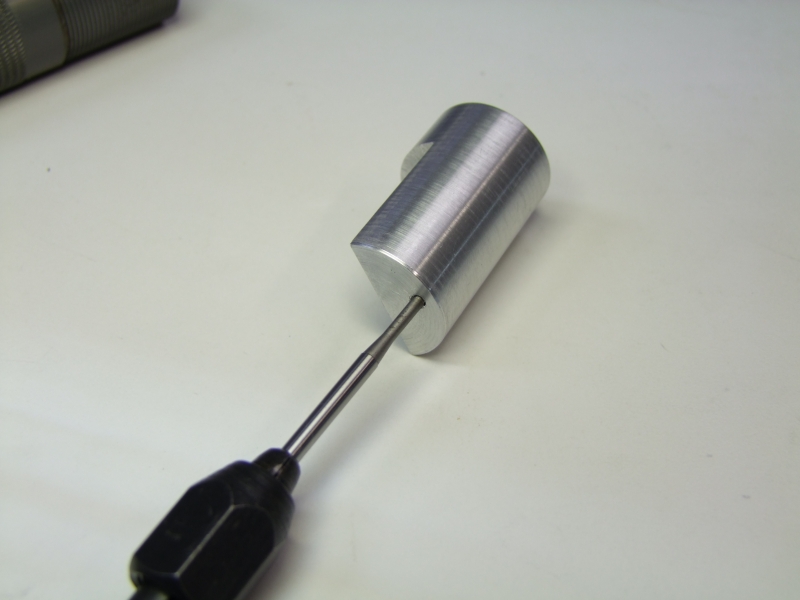
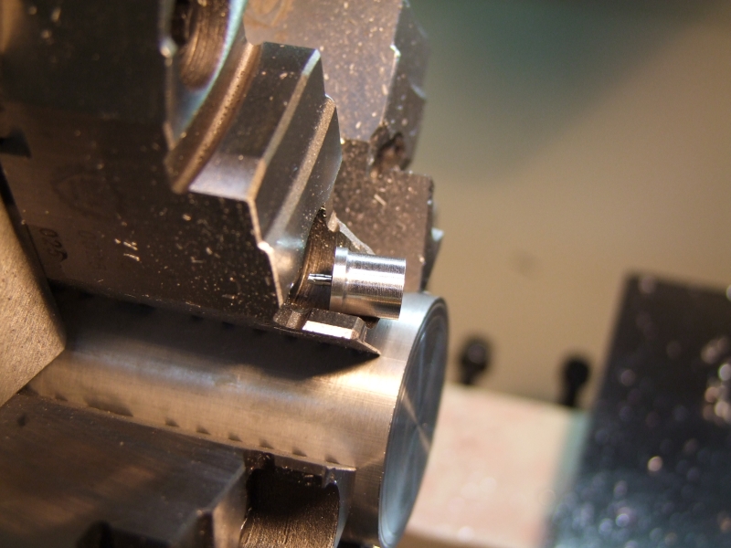
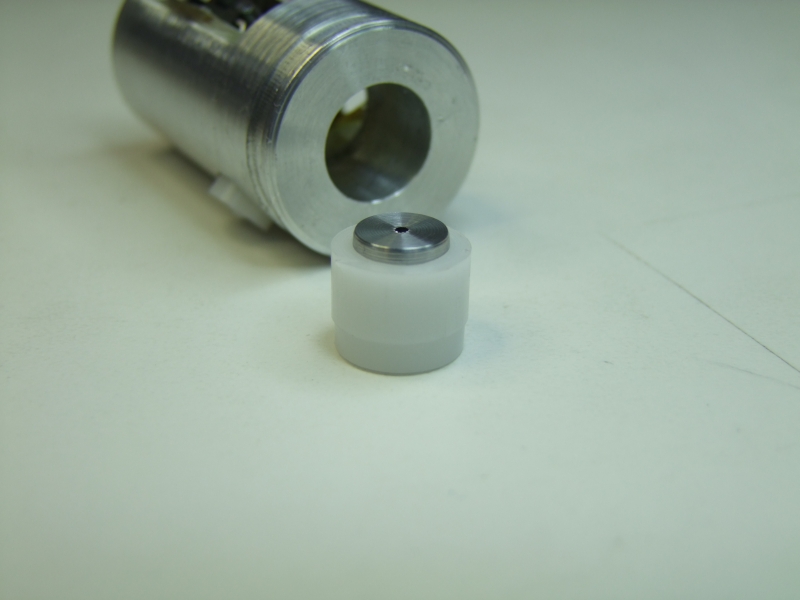
Making the new center Al plug:
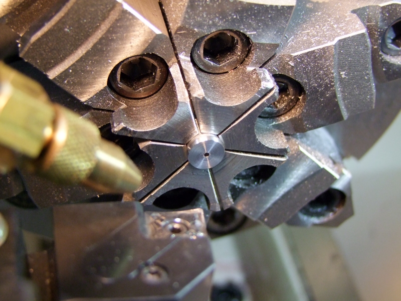
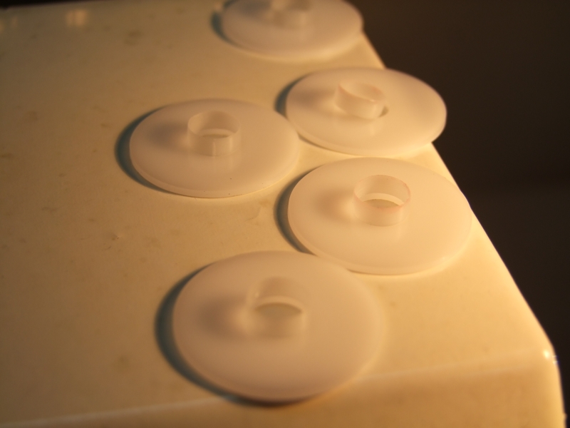
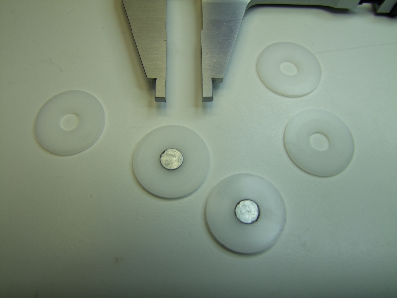
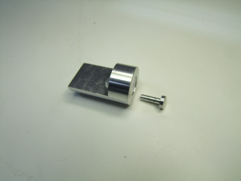
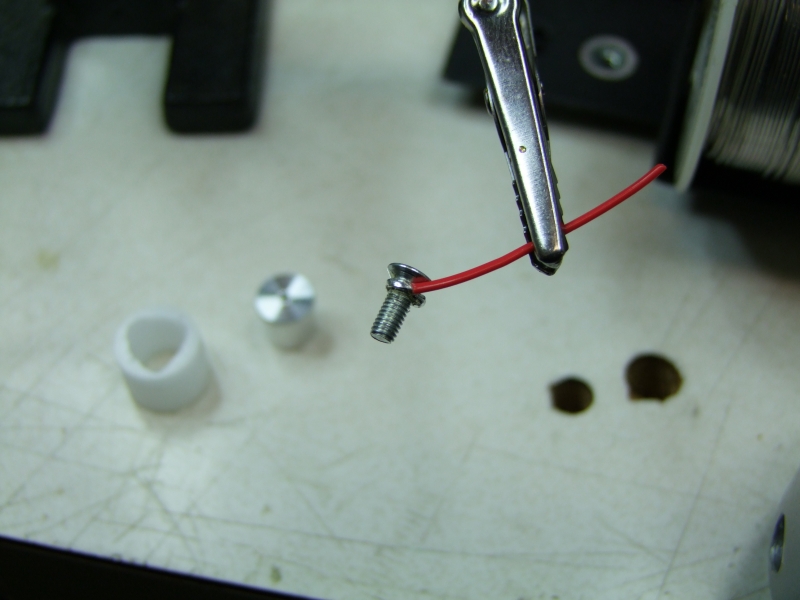
And here are the new pieces:
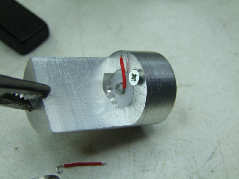
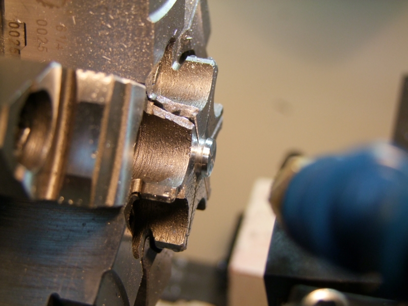
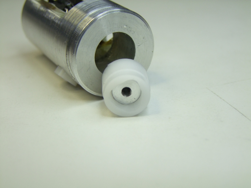
The scalop edges visible here will provide a mechanical hold for the epoxy to that there can't be any rotational forces that would affect the "+" electrical connection:
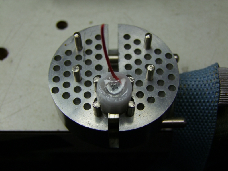
And another quick test to make sure everything is still working fine:
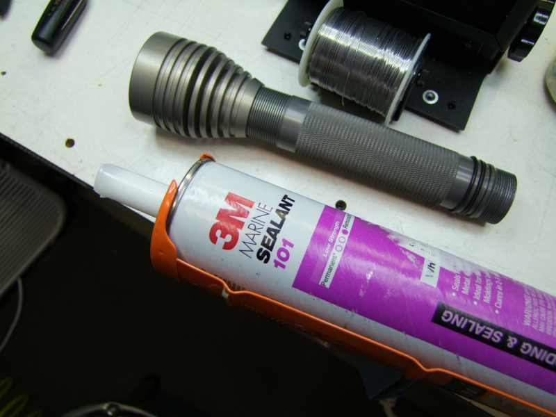
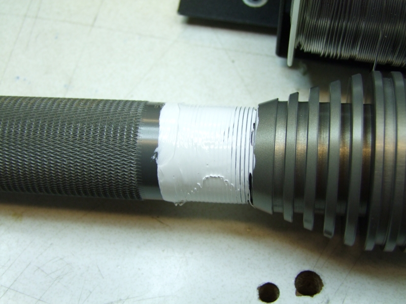
I then sealed the head (this is a diving-rated host after all):
Now that I have taken care of the Bat "+" contact, I took care of making a much stronger Bat "-" contact by adding one extra screw between the head and the heatsink, and one additional screw tying the heatsink, the head, and the main tube/body:
After all of these "extra" steps, everything is just solid, perfectly reliable. Since I am doing an SST-50 version of this host for the same customer, the next version will go much quicker and smoother :twothumbs
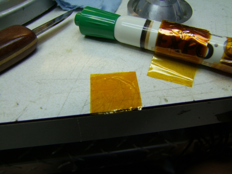
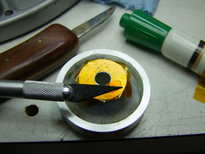
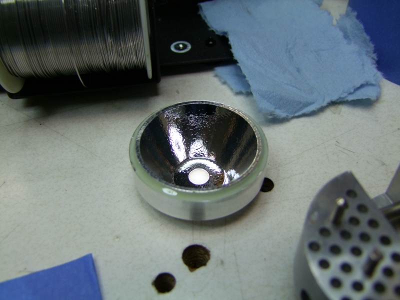
I took two layers of Kapton tape to further isolate the bottom of the reflector against the LED:
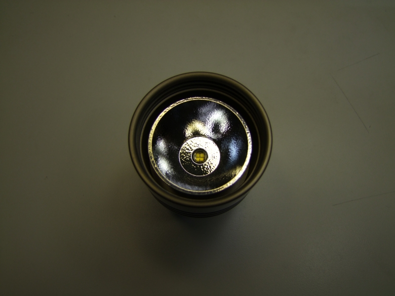
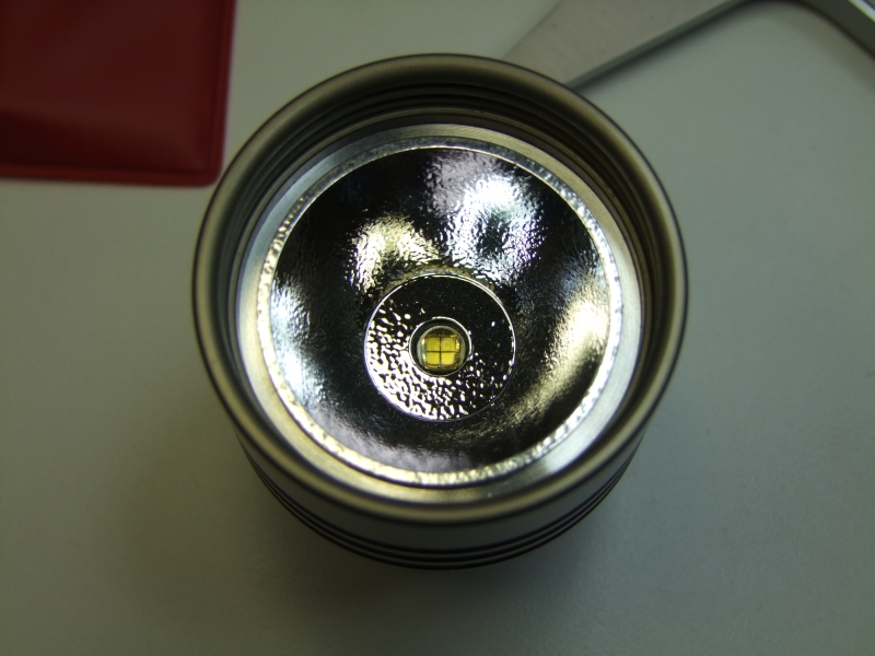
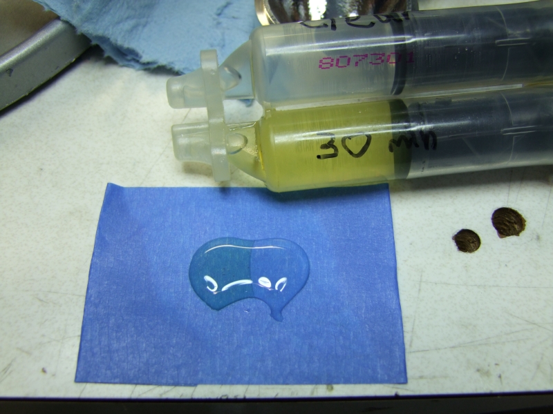
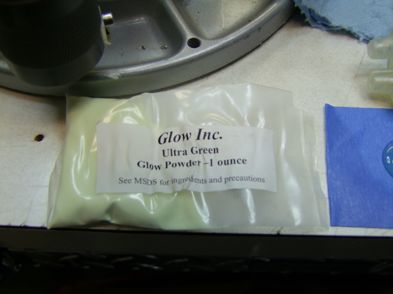
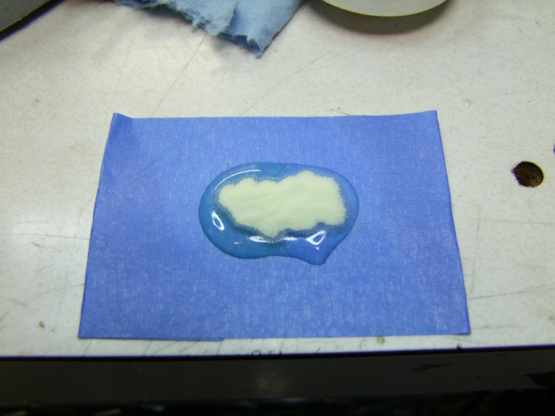
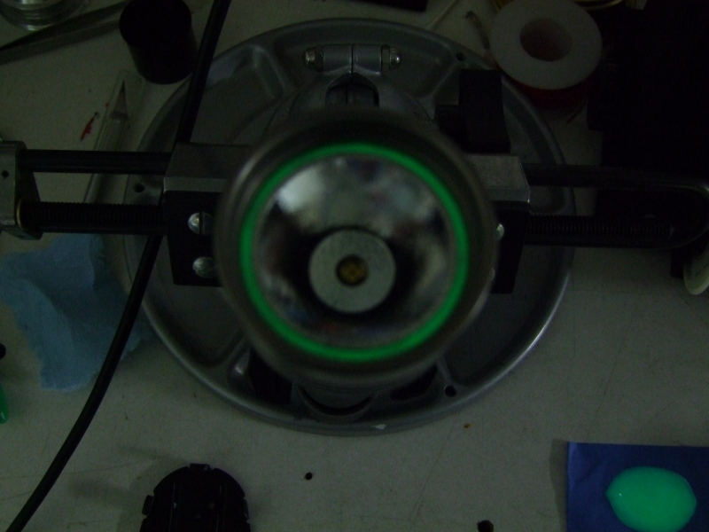
And then used 30min epoxy and Glow powder to attach the reflector to the head:
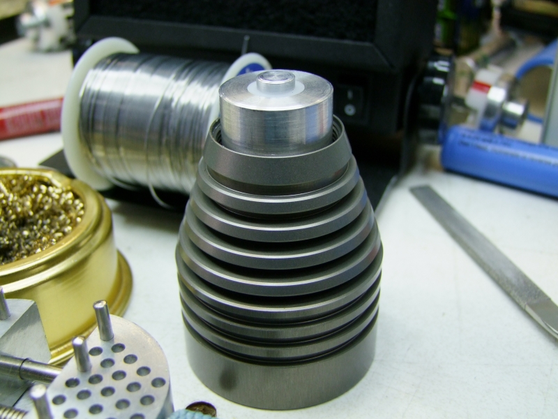
The host is complete, except for one of the o-rings that I am trying to find, but I have not yet heard back from Barbolight on the right size, but hopefully not much longer - I am sure the owner of this light is very eager to get his hands on it ASAP")
Will
It has taken me a LONG time to put this one together, because I was trying to make a regulated version for this host, and the ideal driver (hipCC) fits fine in the larger diameter of the Bomb-proof hosts, but not on the smaller diameter of this U9 host. I did a lot of "experiments" along the way to try different things, so here is a pictorial of the project.
FIrst, I had to get the original U9 host in pieces. Lens was already removed prior to the light arriving to me, but the Barbolight does a good job in making these hosts nearly indestructible, so it was still laborious to get everything separated:
I then had to heat the body/head in my Powder Coating oven to 450F, so that the factory epoxy would soften enough for me to unscrew the head off:
Since I wanted to use the hipCC (about 1.1" dia) and this host was about 1.0" dia, I would have to come up with a custom heatsink. After discussing this a little with George (from www.taskled.com, designer of these drivers) I proceeded to lightly sand two sides of the hipCC to make it fit on the host, but sideways. :
You can see here in my hand written notes my original design:
I then continue work on the mill:
And for the first time I was able to test the fit of the hipCC on the new custom heatsink:
Here is a close-up of the heatsink next to the original paper design:
I continued to make progress on the inner part of the heatsink, which would be composed of a Delrin sleve, with an Al center piece to carry the "+" from the battery to the driver:
Here I am working on the inner Al piece:
The pieces:
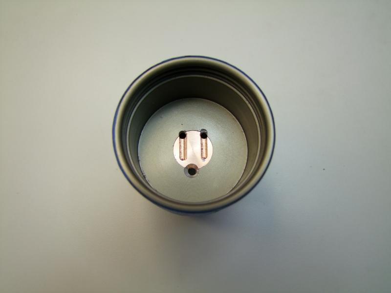
Making a small groove to wire/solder the wire that will be going to the driver:
I then drill and tapped the location for the screw that will carry the Bat "-" to the driver:
I then drill a hole in the head that will mechanically keep the heatsink in position:
and then used the head to transfer punch that location to the heatsink:
I then drill and tapped that hole in the heatsink:
then counterbore the hole to make sure the screw head would be flush with the head (to prevent it from contacting the reflector later on):
Having done this one project, I would not do it again this way, but I decided to install a copper disk for the LED:
I left a thin self to help keep the press-fit copper heatsink in place:
I used my long jaw calipers (thanks Barry!) to measure the hole:
and then make a custom thin heatsink from C110 copper:
And here is how it looks once in place once epoxied in place:
Here I am trying the MC-E to line up where I will be doing the milling cuts:
Doing the actual milling cuts (these allow me to position the wires even lower than normal so that they would be even less chance of a short circuit with the metal reflector - I don't want to leave anything to chance):
I used the Barbo copper heatsink (which is perfectly centered in the head as a guide to center and epoxy the emiter to the head:
The reflector is perfect in terms of height, but not diameter-wise, so I need a centering ring:
This was my initial attempt at securing the Bat + to the wire going to the driver. It did not work as good as I hoped, so I did it again (see further below):
I wired the rest of the wires:
Then used thermal tape to provide a thermal path for the driver:
And then I tested the driver (LED being an SST-50 emiter):
Input voltage/current:
Output current going to the LED:
I used epoxy to keep everything in place:
and then tried on the actual head/host:
The AW 26500 cells that the owner wanted to use were a tad larger in DIA than the host (this being a "C" size host), so I bored it out slightly:
I was having some intermitent behavior (more on this shortly), so I added a flat spring to the heatsink body to aid with the Bat "-" connection to the heatsink. I first made a press-fit Delrin collar to keep the heatsink in place safely:
and then cut a groove for the flat spring (yup, the discarded negative contact from a Mag host - how is that for recycling!):
I also cleaned up the tailcap:
I decided I needed a better spring solution as it was not a great match for these cells. I used silver conductive epoxy to attach it to the tailcap:
As I still had the same intermitent contact, I decided to re-do the Bat "+" contact by using a small screw instead, so that meant re-doing that section of the heatsink. Here I am enlarging the hole in the Delrin sleeve to allow for a larger Al center piece :
Here I drilled a side hole and made a small delrin plug to limit the travel of the new Pos plug:
Making the new center Al plug:
And here are the new pieces:
The scalop edges visible here will provide a mechanical hold for the epoxy to that there can't be any rotational forces that would affect the "+" electrical connection:
And another quick test to make sure everything is still working fine:
I then sealed the head (this is a diving-rated host after all):
Now that I have taken care of the Bat "+" contact, I took care of making a much stronger Bat "-" contact by adding one extra screw between the head and the heatsink, and one additional screw tying the heatsink, the head, and the main tube/body:
After all of these "extra" steps, everything is just solid, perfectly reliable. Since I am doing an SST-50 version of this host for the same customer, the next version will go much quicker and smoother :twothumbs
I took two layers of Kapton tape to further isolate the bottom of the reflector against the LED:
And then used 30min epoxy and Glow powder to attach the reflector to the head:
The host is complete, except for one of the o-rings that I am trying to find, but I have not yet heard back from Barbolight on the right size, but hopefully not much longer - I am sure the owner of this light is very eager to get his hands on it ASAP
Will
Last edited: