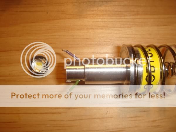
Another Cree XP-G mod .... Tower Module

tx101

Flashlight Enthusiast
Joined
May 17, 2008
Messages
2,364
Location
London UK
After a couple of posts from member Justin Case, I decided
to have a go at building a Tower Module with a Cree XP-G R5
Without his advice I never would have attempted this build
so kudos to Justin for spoon feeding me :D

The R5s I received where purchased by member R@ndom from
Cutter. These are the R5s mounted on a 10mm board.
For the R5 to fit thru the Turbo head opening, the board had to
be reduced in size. I used pair of snips and to finish off, a file.
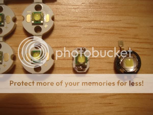
DSC01831.jpg


For size comparison, the emitter on the right is a SSCP4

Unfortunately, I did not have any spare empty Tower Modules
so I had to cannibalize a previously build Module
DSC01834.jpg


Here is the unfortunate donor

DSC01836.jpg


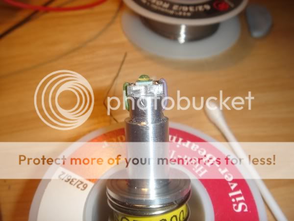
I used a very sharp blade and managed to remove the old emitter
intact.

DSC01837.jpg


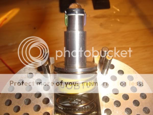
The R5 has now been AAed to the Module

DSC01846.jpg


Now sitting inside a KT-4 head :devil:

DSC01824.jpg


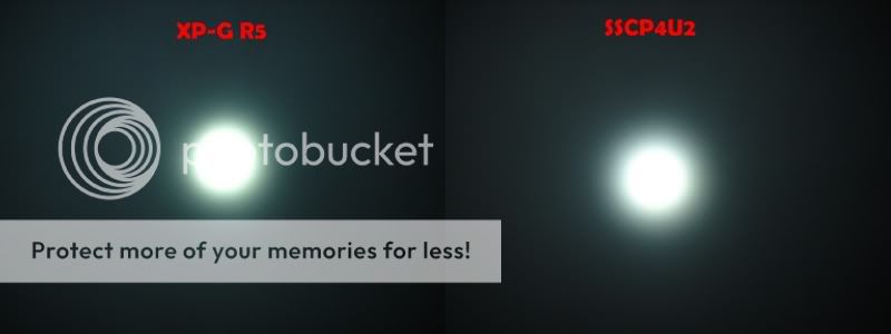
Before and after whitewall beamshot ..... hmm they look more or less the
same in the photo ?


From my own personal observations, I have build Tower Modules using
SSCP4s, Diamond Dragons and K2 TFFC they all have similar looking
beams. The R5 and P4 are almost identical, it is a shame I had to cannibalize
the Module with the SSCP4, otherwise I could have taken
some outdoor beamshots comparing the two.
When compared to a Module with a K2 TFFC emitter, the R5 is brighter
and going from memory the K2 TFFC was brighter than the P4.

Wow if this is brighter then a K2 that is something! The K2 is quite a thrower in itself.
 
Nice work. Good idea to use snips to speed up the trimming. Why did you choose to trim the MCPCB into the oblong shape, instead of a smaller diameter circle or even a less oblong shape?

See this XP-G tower build (not mine) for comparison. I like your approach of running the hookup wires straight up, without having to bend them around the emitter.

It seems that potentially a Lux focus AW tower might have a more optimum stem height than a Seoul focus tower. I've found that small focus height differences can result in small changes in hot spot lux, although the beam looks the same to the naked eye. Do you have a lux meter or a Canon P&S camera plus CHDK firmware to compare the hot spots for the XP-G vs P4?

At 1000mA drive current, the XP-G R5 should deliver about 100 emitter lumens more than a P4. Can you see a difference in a ceiling bounce test? Also, the XP-G should have lower Vf than a P4, resulting in a lower tail current draw. Do you measure a difference with a DMM?
 
Last edited:
Nice work. Good idea to use snips to speed up the trimming. Why did you choose to trim the MCPCB into the oblong shape, instead of a smaller diameter circle or even a less oblong shape? oblong was the quickest and neatest. I did not want to use a
file to make it nice and circular because I was concerned I might damage
the dome.

See this XP-G tower build (not mine) for comparison. I like your approach of running the hookup wires straight up, without having to bend them around the emitter. I used a SSC P4 as a guide to how much of the MCPB
I had to remove. I managed to remove enough so that the R5 was a
couple of hairs smaller than the P4, then I knew that the wires would not
cause any problems going thru the reflector opening

It seems that potentially a Lux focus AW tower might have a more optimum stem height than a Seoul focus tower. I've found that small focus height differences can result in small changes in hot spot lux, although the beam looks the same to the naked eye. Do you have a lux meter or a Canon P&S camera plus CHDK firmware to compare the hot spots for the XP-G vs P4? No sorry, I do not have a Lux meter or camera that will let
me measure

At 1000mA drive current, the XP-G R5 should deliver about 100 emitter lumens more than a P4. Can you see a difference in a ceiling bounce test? Also, the XP-G should have lower Vf than a P4, resulting in a lower tail current draw. Do you measure a difference with a DMM?
The problem is that the R5s I recieved have a very green tint (yuk!!!)
where as the P4, to my eyes has a very vanilla tint so will that effect the
way our eyes perceive how bright each beam is because they both look
about the same to me.
I should have taken some measurements before I swapped out the emitters :(
Using a Fivemega 2 x C body with DX 25500 cells, I am getting 0.73A
at the tailcap

I hope the triple XP-G R5 I ordered will have a good tint.

0.73A at the tailcap is about 50% higher than what I've measured for multiple AW towers using Seoul P4 U2SWOH-bin LEDs and SOB1000s. For those, I consistently measure just under 0.5A at the tail for 2xLi-ion. Your result is very surprising considering the datasheet claim that the XP-G's Vf at 1000mA is 3.3V. Do you have a high contact resistance somewhere in the circuit path?
 
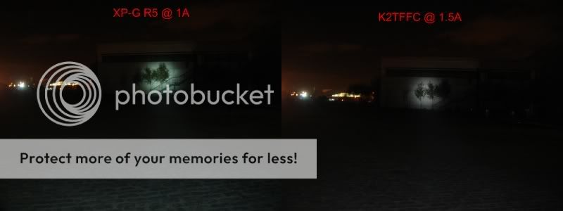
A beamshot comparing the XP-G R5 @ 1A against a K2 TFFC @ 1.5A

XPGvsK2.jpg

Wow! That is a huge difference. The spot is larger and more intense and using less power than the K2.

It looks like the XP-G is a thrower after all in the correct reflector setup. Thanks for the testing. Now I want a tower!
 
I hope the triple XP-G R5 I ordered will have a good tint.

0.73A at the tailcap is about 50% higher than what I've measured for multiple AW towers using Seoul P4 U2SWOH-bin LEDs and SOB1000s. For those, I consistently measure just under 0.5A at the tail for 2xLi-ion. Your result is very surprising considering the datasheet claim that the XP-G's Vf at 1000mA is 3.3V. Do you have a high contact resistance somewhere in the circuit path?

I got similar results measuring SSC P4 as you did (remember the PM I send you :D )
With the same host and cells, with a K2 TFFC @ 1.5A, the tailcap is
measuring 0.82A
 
I remember now. :thinking:

So the question remains as to why the tail current seems much higher than expected. Can you put your DMM across the LED terminals to measure Vf?

BTW, what is the approx range to that bldg in the beam shots?
 
Last edited:
I remember now. :thinking:

So the question remains as to why the tail current seems much higher than expected. Can you put your DMM across the LED terminals to measure Vf?

BTW, what is the approx range to that bldg in the beam shots?

Vf across the LED is 3.10V
The distance to the building is 50 meters (164 ft)
 
Vf across the LED is 3.10V
The distance to the building is 50 meters (164 ft)

Nice Vf and throw.

I just completed one AW Seoul focus tower with an XP-G R4 bin from nailbender. The XP-G came on a 10mm round MCPCB, so I had to grind it down to fit. I used the famous tx101 method of snipping away the MCPCB into an oblong shape. I had an SOB1227 available, so that's what I used. The SOB measured out to 1196mA drive current. I filed down the MCPCB by 0.4mm to match the XP-G die height with that of a Seoul P4.

Compared the tower to two other towers: 1) AW Seoul focus tower with an SOB1000 and a Seoul P4 U2SWOH-bin LED, and 2) AW Seoul focus tower with an SOB1000 and a 2S2P Cree MC-E K-bin (mounted on an 0.7mm shim to raise the MC-E die height).

Results:

Code:
                Lux at 1 meter
Emitter/TH    SRTH   T-62   KT1/2   Itail (A)   Vf (V)
P4, U2SWOH   14000  11100   10800   0.49        3.40
MC-E K-bin    9500   7200    7800   0.82        6.22
XP-G R4      20300  15100   14200   0.58        3.28

The XP-G focuses to a very bright, tight hot spot. Also, the XP-G spill at the beam midpoint measured 145 lux in the SRTH, compared to 70 lux for the P4 tower.
 
Looking at your results, the XP-G is significant improvement over the
P4 in terms of brightness.

Here comes a stupid question, comparing the XP-G to the P4, the current
for the XP-G is higher but the Vf is lower, so how does that effect the runtime
when compared to the P4 ?
 
Remember, I'm using an SOB1227 driver (only because that's what I had available). If I had been using an SOB1000, the XP-G R4 Vf would probably be even lower -- let's say 3.1V like you found. Then, the LED power draw would be only about 3.1W and the tail current draw would certainly be less than the ~0.5A for the P4 tower (for which the LED draws about 3.4W). Clearly, run time for the XP-G would be better than for the P4.

For the SOB1227/XP-G case at hand, the tail current draw for the XP-G tower is 0.58A, so I would expect the run time to be a little less than that for the 1000/SOBP4 tower. But output is substantially increased.
 
tx101,


That looks very promising!:faint:

I have an order for some drivers, and will be building a tower module very much like yours!

I can't wait to see how it does in a Surefire 3" Turbohead!:devil:

Thanks for posting your mod and sharing the info!:wave:
 
tx101, it is interesting that you get a Vf of 3.10V at a nominal 1000mA drive current, but a tail current of 0.73A. Am I correct in understanding that this same tower, when it had a P4, drew about 0.5A at the tail? In my small sampling of SOB1000 drivers, I've typically measured a driver efficiency of 85% or better. So I would have expected your XP-G to draw about 0.45A at the tail.

My XP-G R4 tower, running at Vf=3.28V and 1196mA draws 0.58A at the tail using 2xIMR26500 in a FiveMega host.

Maybe your DX Li-ion cells are suspect?
 
I just tried the module with a different setup,
a Leef body with 2 x AW 18500 cells
The results are VF 3.10v across the emitter
and 0.8A at the tailcap

It is the same Module that originally had a SSCP4

Might be an idea to measure the current at the emitter ?
but I will not be able to get the soldering iron out until Saturday
evening (I have a rampaging 2 yr old son running around :) )
 
Top