wquiles
Flashaholic
On my last Barbo host project, I used a P7 and a P7 reflector:
http://www.candlepowerforums.com/vb/showthread.php?t=222258
For this one, the owner wanted to use the MC-E, and the very hard to find McGizmo 45mm reflector (McR45):
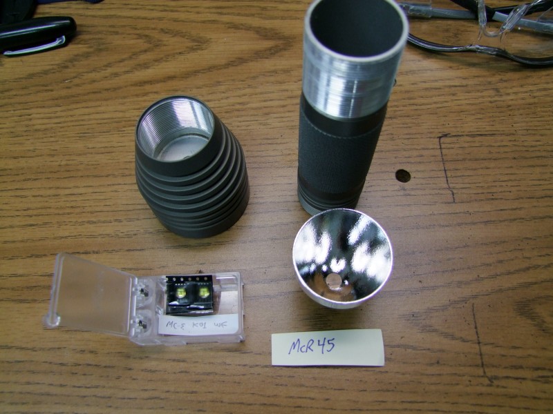
As with many of these projects, this is a combination never tried before, so I was not sure how it was going to work until the very end. Lets get started ...
Like before, I need to make a large hole in the head (where the built-in heatsink is located) since the reflector is very deep - in fact, this reflector sits significantly deeper than the P7 I used earlier:
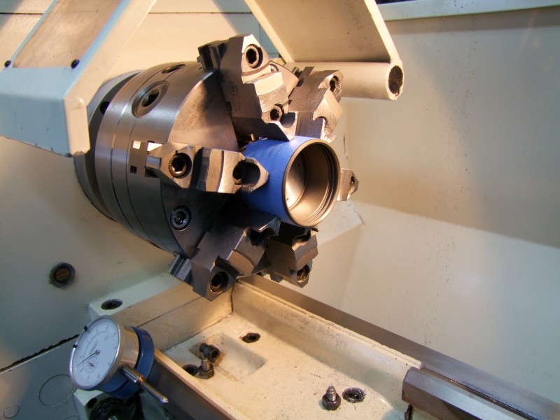
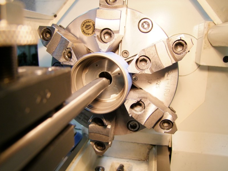
As you can see here, I still need to cut more, as it is not yet flush with the lens groove:
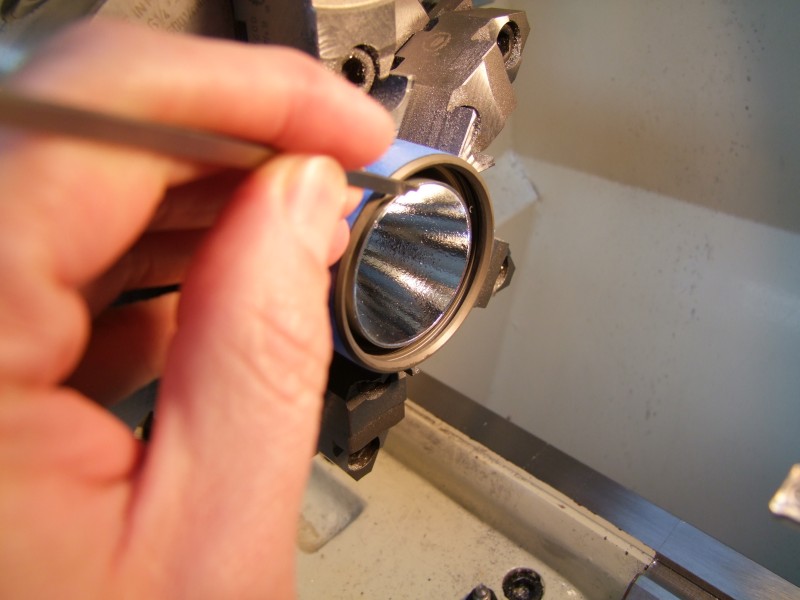
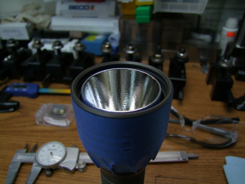
Not only do you need to cut in the head, but the reflector itself has to also be trimmed since a good portion resides inside the main body:
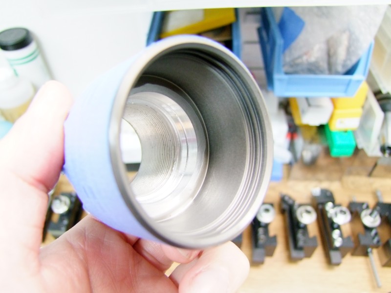
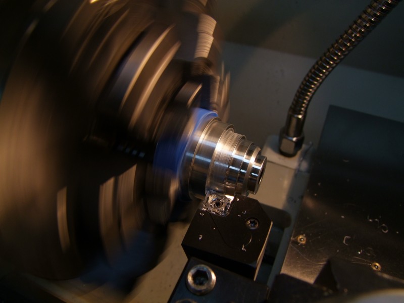
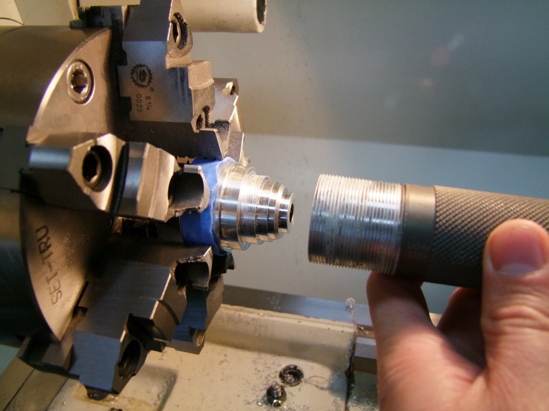
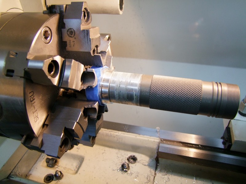
And after many cut-and-tries, it finally fits:
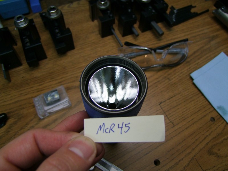
Now, lets deal with the MC-E. Unlike the P7, the LED and the LED dome are smaller, so I can't use the reflector to center the LED:
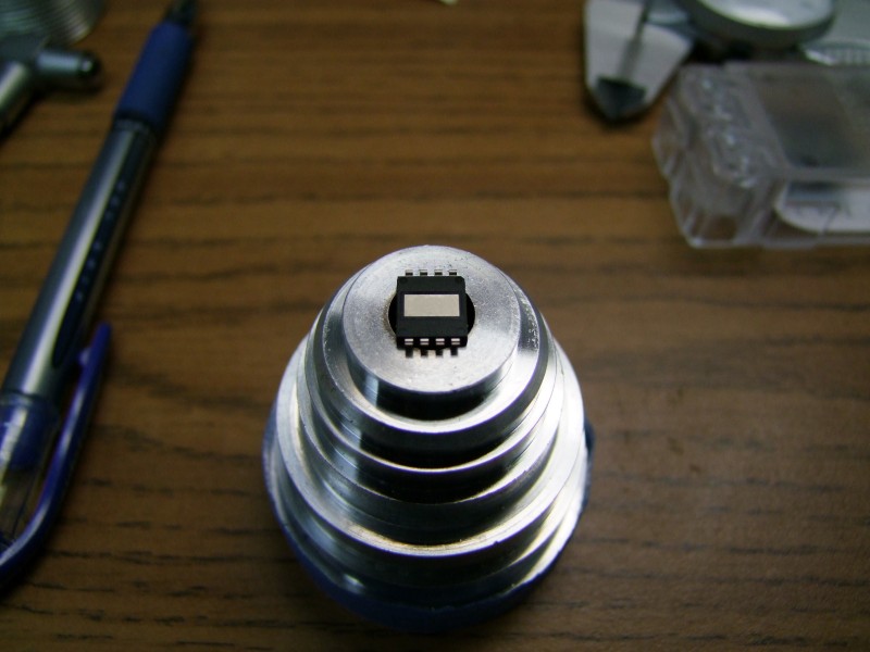
To provide a really good and strong mounting to the heatsink, I decided to use a "star":
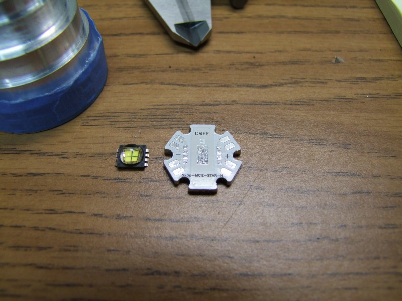
With my new bench pin-vise (thanks to forum member darkzero), I proceeded to solder the emiter in place:
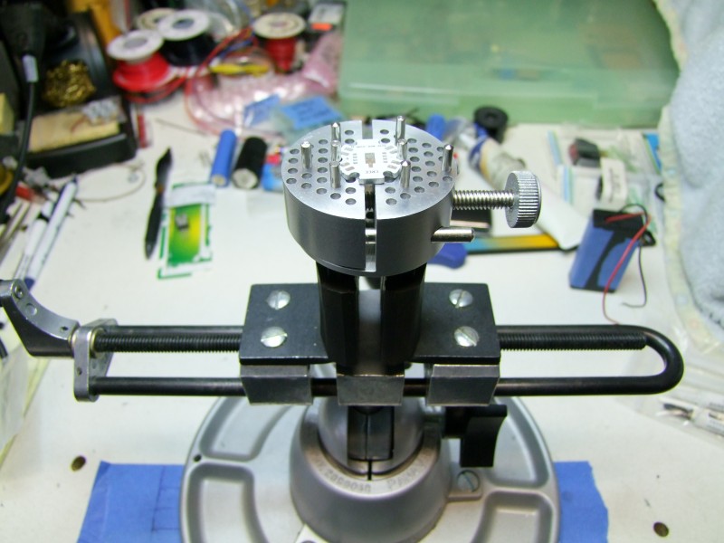
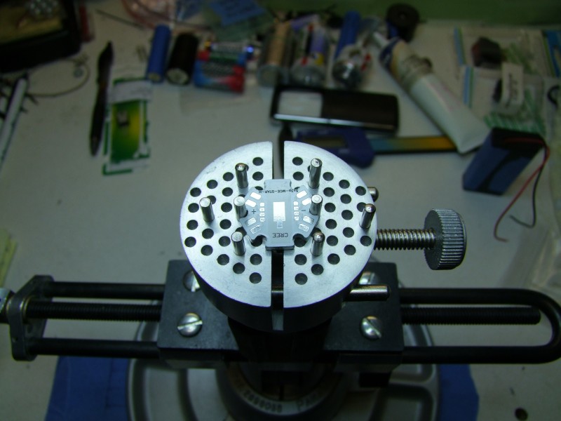
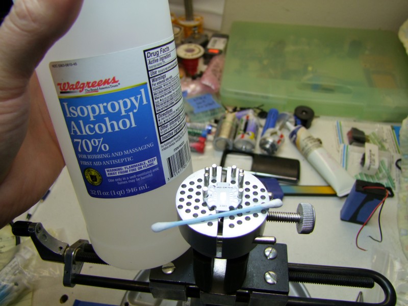
First clean emiter and star:
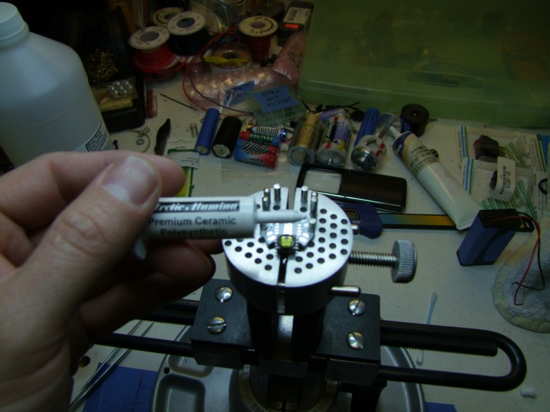
Then apply thermal paste. I am not using epoxy, since the emiter will be soldered at 8 points - that should be enough
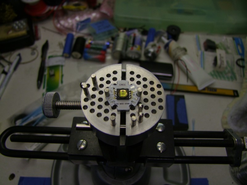
Now that I had the emiter on the star, I started playing with the focus, only to find that it was not focusing well (the McR45 is the best LED reflector I have ever used, but it was not designed for the MC-E!). So I had to raise the emiter, slowly, by trimming from the reflector in light pases - needless to say, this took a LONG time:
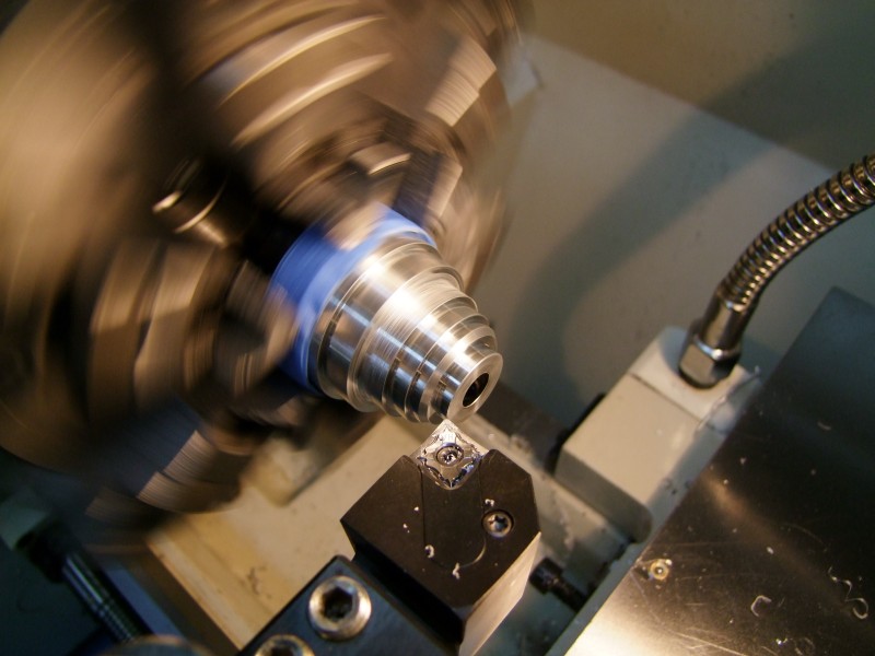
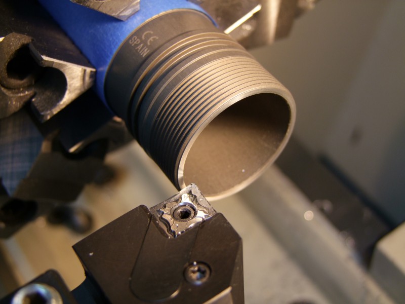
I then cleaned the edge of the main tube for a good electrical contact:
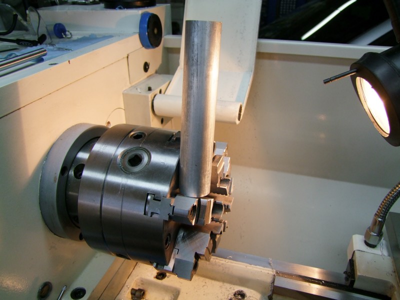
And then proceeded to create from scratch a new heatsink. Note that in trying to make a simpler assembly, I am no longer using a threaded heatsink. I will be using a press fit heatsink, with a hidden set screw to still guarantee a "bomb proof" design
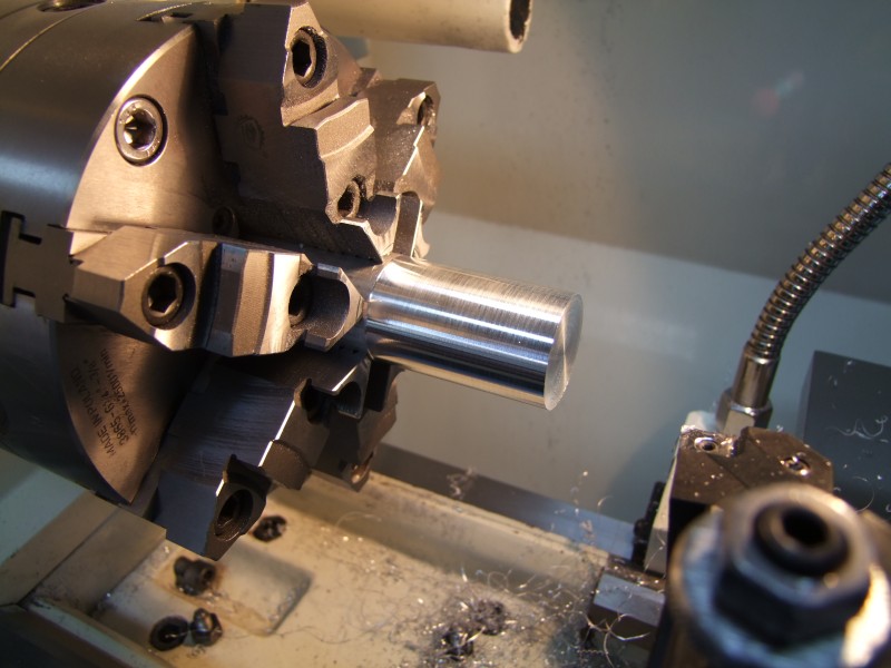
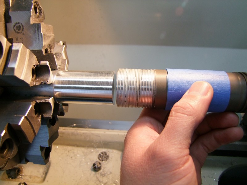
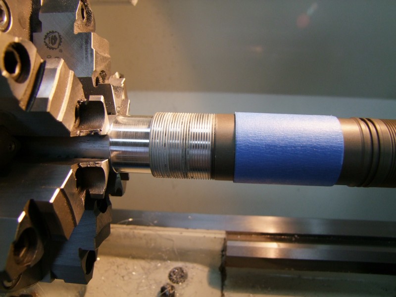
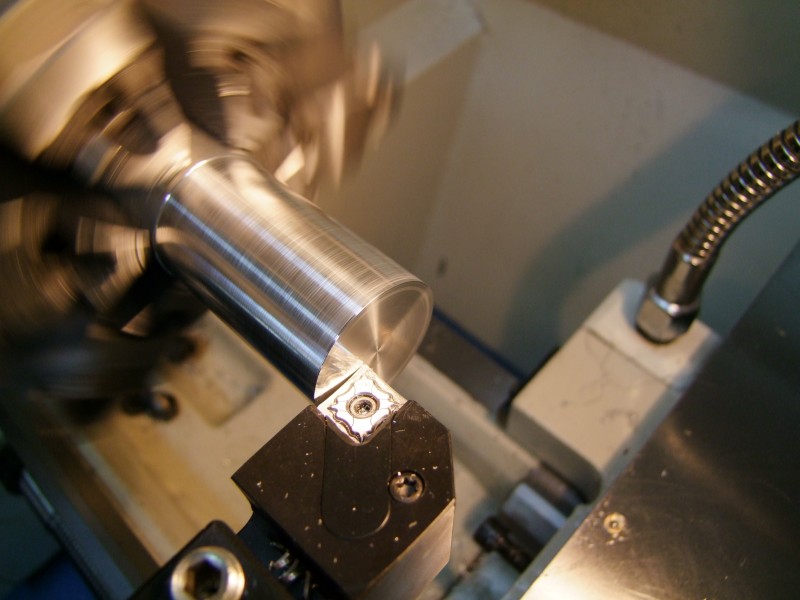
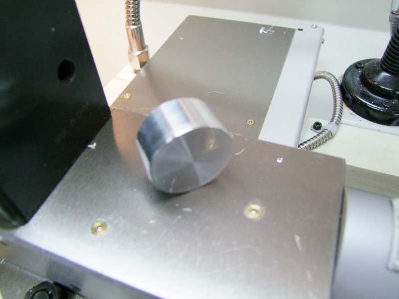
I then milled a pocket for the positive contact/spring assembly - can you tell where it comes from?:
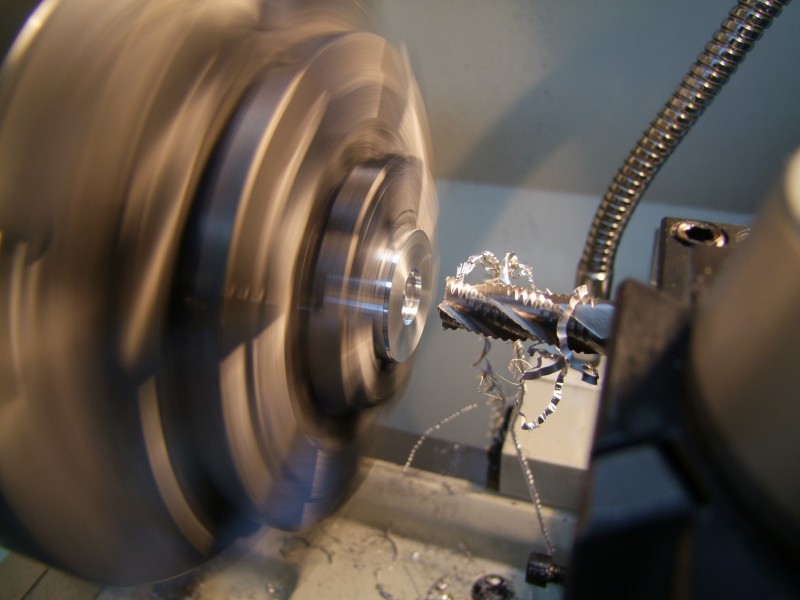
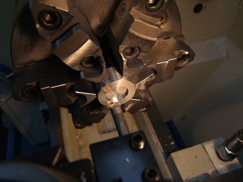
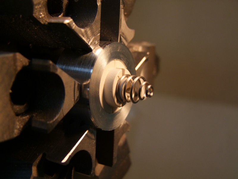
Here is the assembled heatsink/emiter/plug:
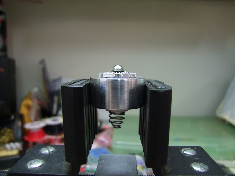
For the positive contact I made a hole all through the heatsink, and for the negative, I threaded a small blind hole:
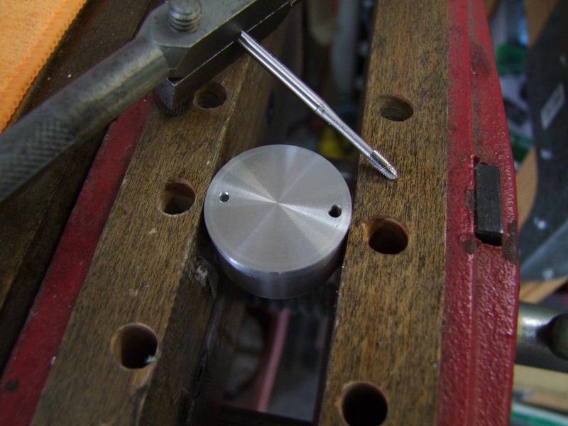
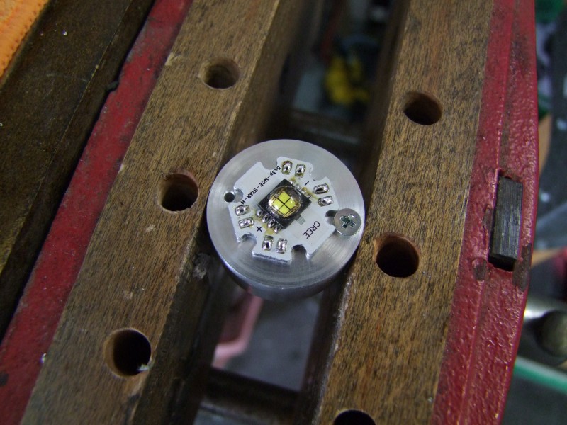
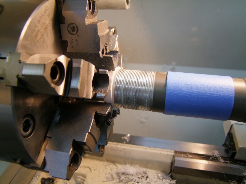
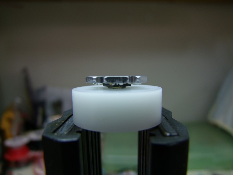
Now that I am ready to get the emiter epoxied to the heatsink, I need a way to center it, so I made a delrin centering "adapter":
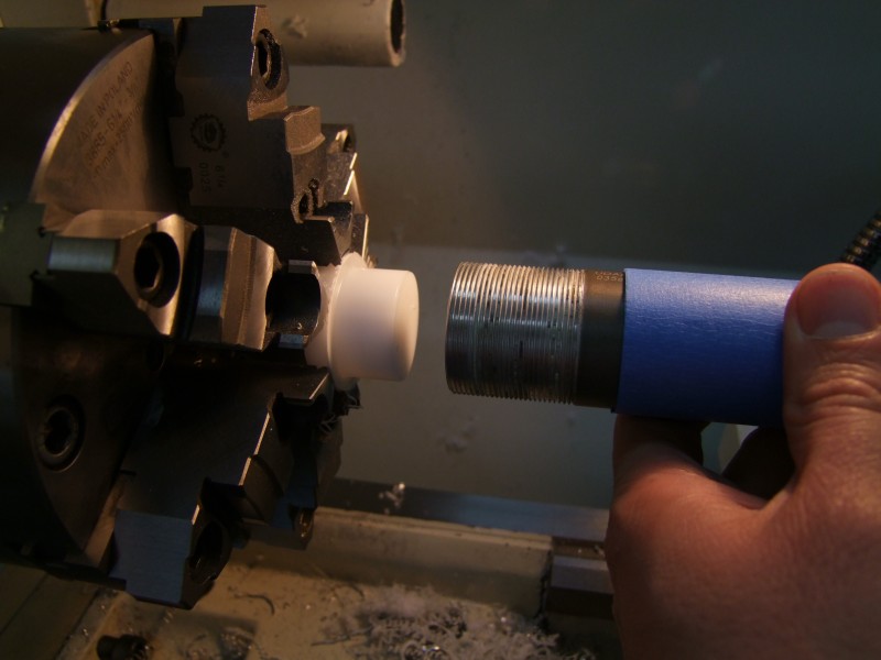
Prepare the epoxy:
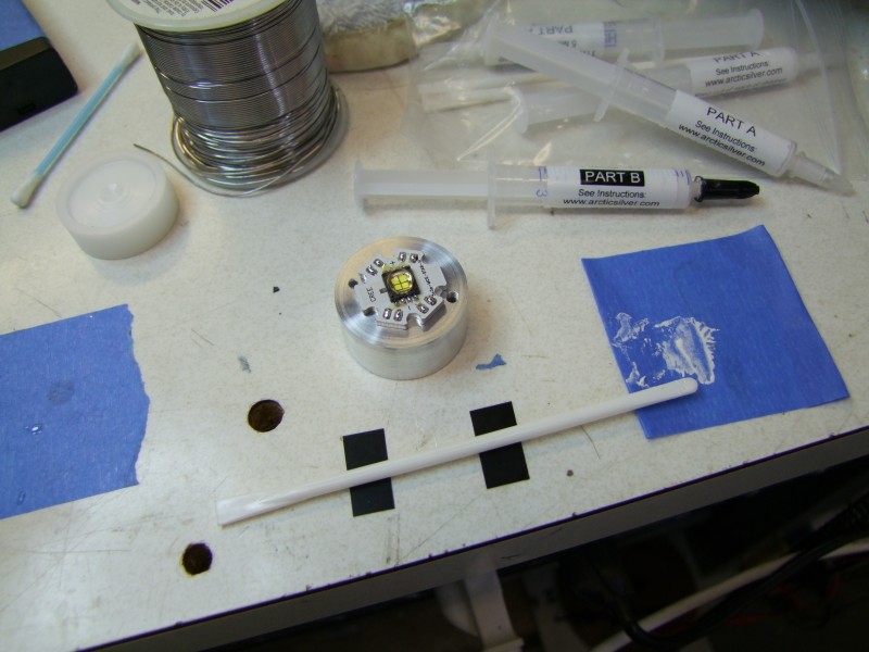
get it inside the tube:
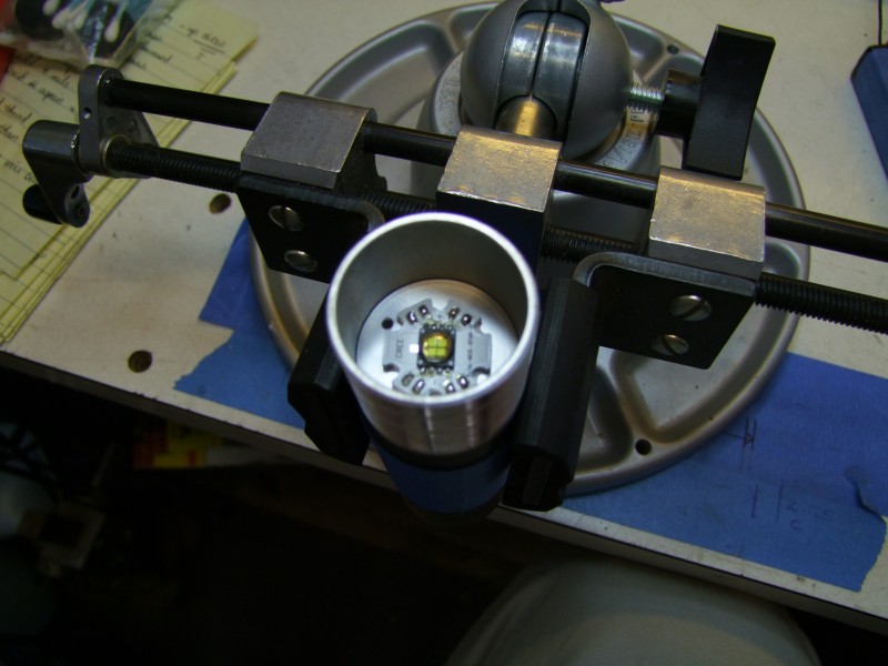
place adapter in place, gently rotating it to get the emiter centered:
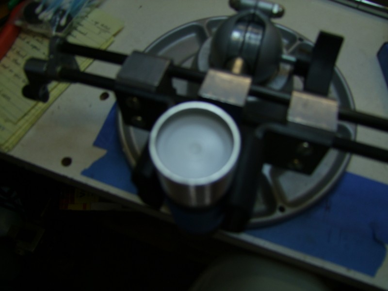
and momentarily apply light pressure to seat the emiter in place:
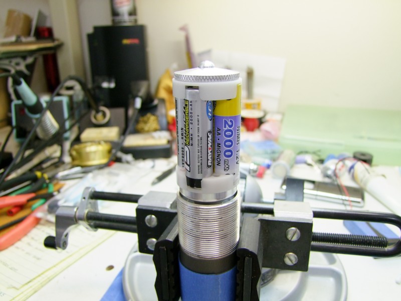
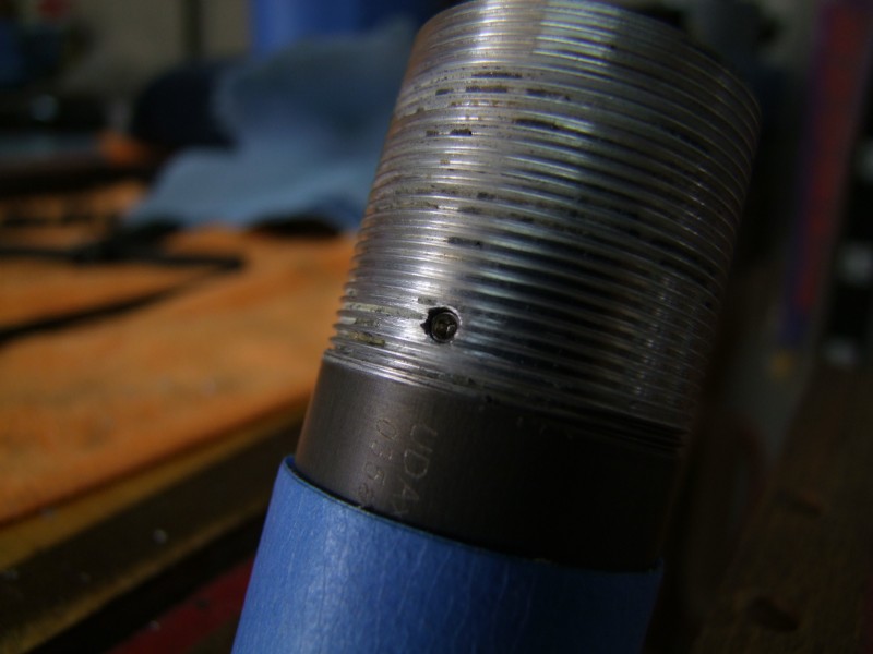
Here I am drilling and tapping the body and the emiter, once I figured out the right position inside the body:
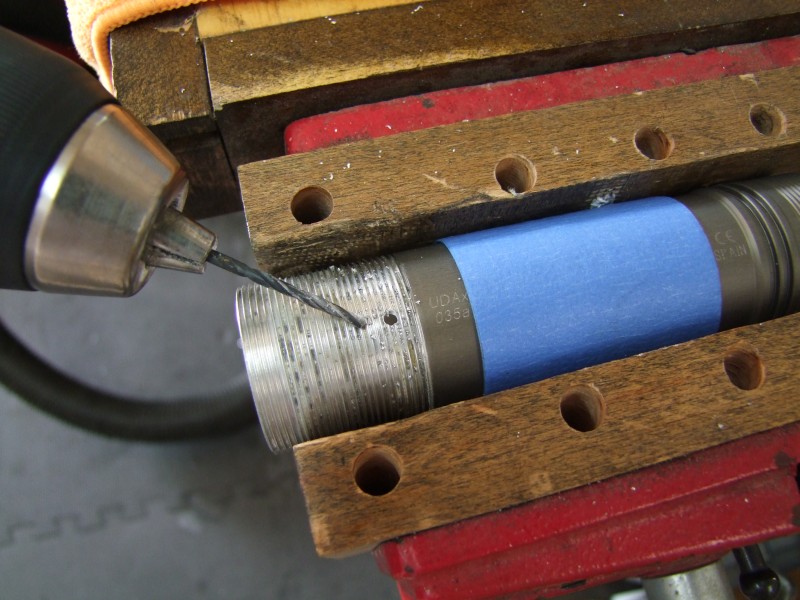
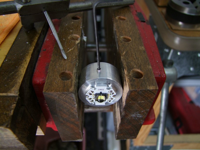
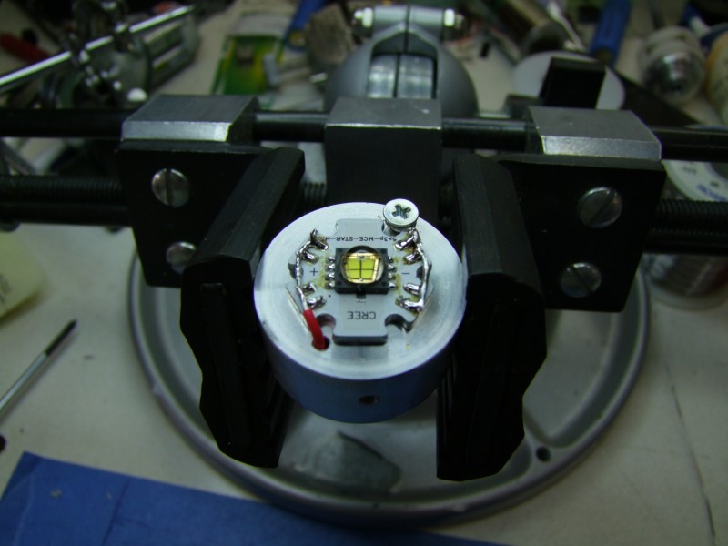
Then solder the wires on top:
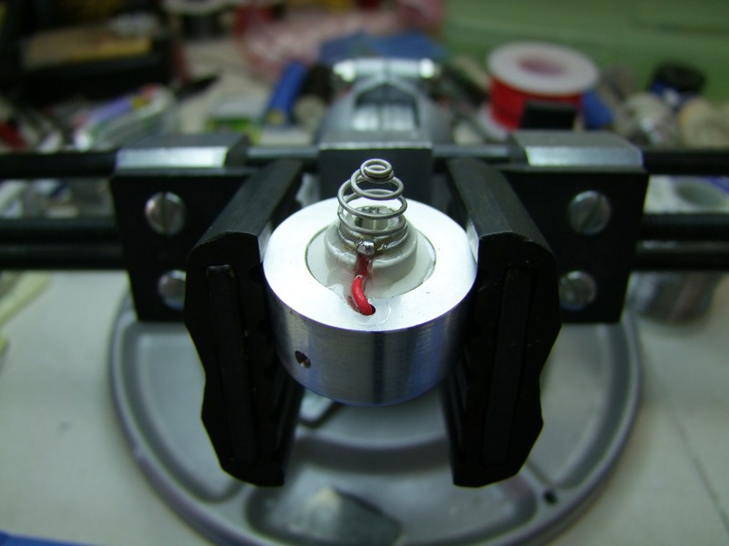
and get the spring ready in the bottom:
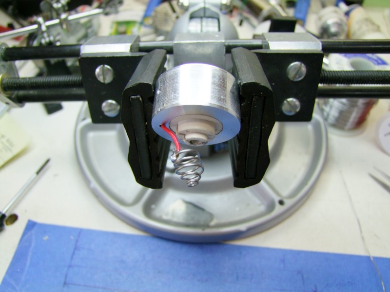
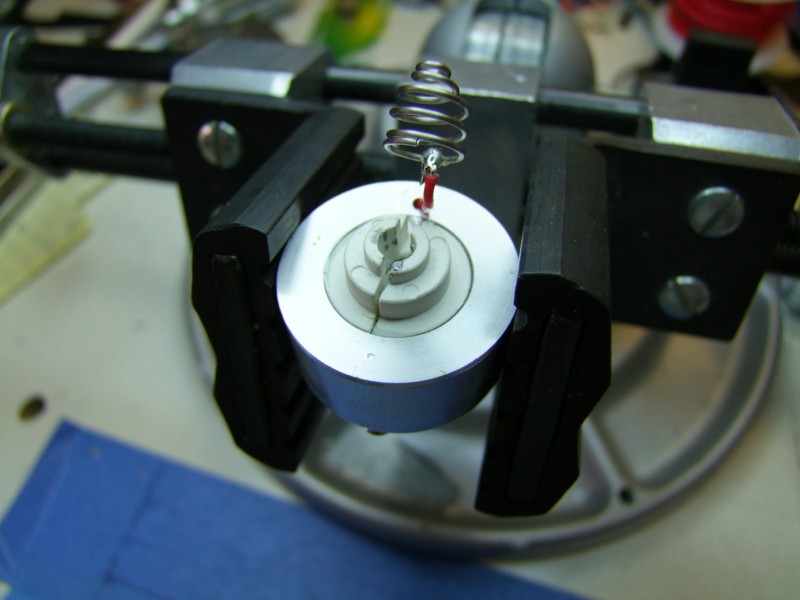
Epoxy the plastic base, spring, and wire in place:
Apply krapton tape to prevent a short from emiter and reflector:
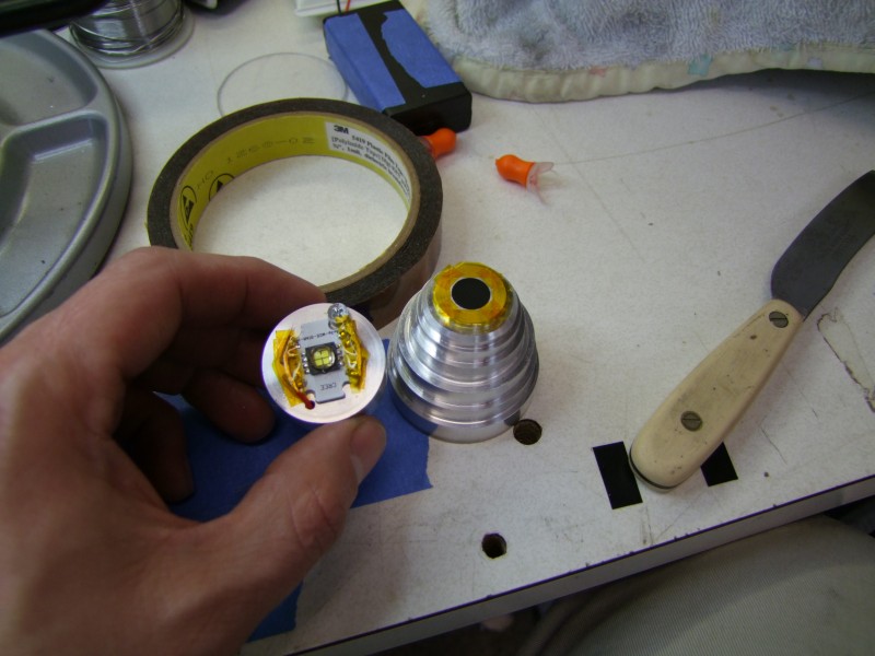
Apply a light coat of thermal epoxy to the "plug":
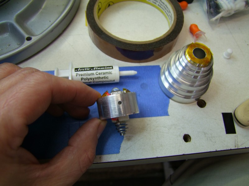
Apply high-temp silicone to keep the reflector in place:
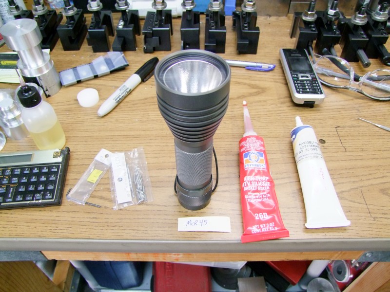
And finally put the battery and see if this contraption works!:
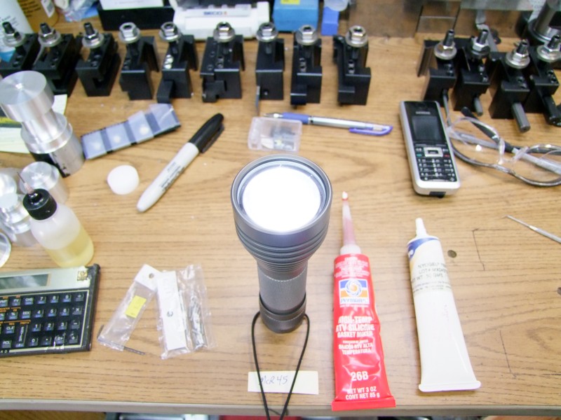
EDIT: just took some beamshots. Fujifilm Finepix S100FS, on tripod, on manual mode (F2.8 @ 2sec), lens set to full wide angle. Both the 18650 cell in the P7 and the A123 in the MC-E are charged.
1) First WQ Barbo Host with P7, then WQ Barbo Host with MC-E/McR45:
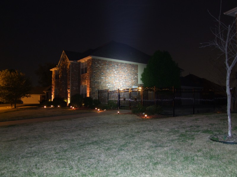

2) First WQ Barbo Host with P7, then WQ Barbo Host with MC-E/McR45:
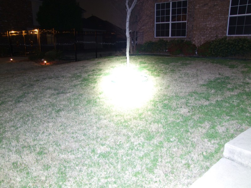
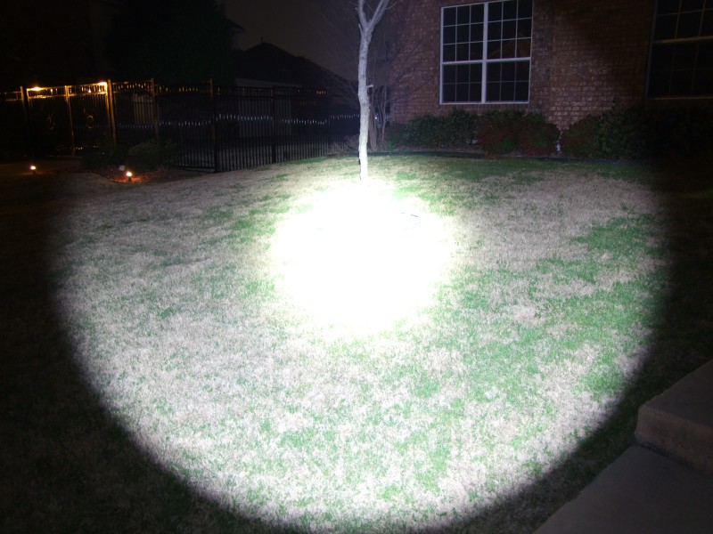
3) First WQ Barbo Host with P7, then WQ Barbo Host with MC-E/McR45:
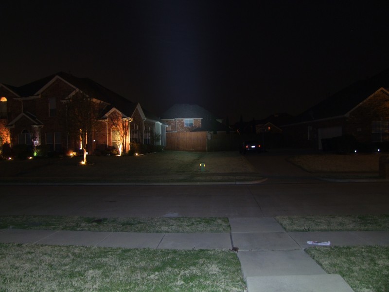
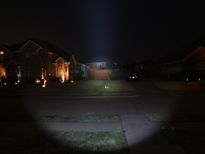
You can see the P7 reflector giving a wider coverage, but the McR45 has more throw and a narrower beam. You can also barely see a little bit of the donut hole in the McR45 reflector, just like with the older 5W Luxeons, but it is not very noticeable.
Will
http://www.candlepowerforums.com/vb/showthread.php?t=222258
For this one, the owner wanted to use the MC-E, and the very hard to find McGizmo 45mm reflector (McR45):

As with many of these projects, this is a combination never tried before, so I was not sure how it was going to work until the very end. Lets get started ...
Like before, I need to make a large hole in the head (where the built-in heatsink is located) since the reflector is very deep - in fact, this reflector sits significantly deeper than the P7 I used earlier:


As you can see here, I still need to cut more, as it is not yet flush with the lens groove:


Not only do you need to cut in the head, but the reflector itself has to also be trimmed since a good portion resides inside the main body:


And after many cut-and-tries, it finally fits:

Now, lets deal with the MC-E. Unlike the P7, the LED and the LED dome are smaller, so I can't use the reflector to center the LED:

To provide a really good and strong mounting to the heatsink, I decided to use a "star":

With my new bench pin-vise (thanks to forum member darkzero), I proceeded to solder the emiter in place:


First clean emiter and star:

Then apply thermal paste. I am not using epoxy, since the emiter will be soldered at 8 points - that should be enough


Now that I had the emiter on the star, I started playing with the focus, only to find that it was not focusing well (the McR45 is the best LED reflector I have ever used, but it was not designed for the MC-E!). So I had to raise the emiter, slowly, by trimming from the reflector in light pases - needless to say, this took a LONG time:

I then cleaned the edge of the main tube for a good electrical contact:

And then proceeded to create from scratch a new heatsink. Note that in trying to make a simpler assembly, I am no longer using a threaded heatsink. I will be using a press fit heatsink, with a hidden set screw to still guarantee a "bomb proof" design


I then milled a pocket for the positive contact/spring assembly - can you tell where it comes from?:


Here is the assembled heatsink/emiter/plug:

For the positive contact I made a hole all through the heatsink, and for the negative, I threaded a small blind hole:


Now that I am ready to get the emiter epoxied to the heatsink, I need a way to center it, so I made a delrin centering "adapter":


Prepare the epoxy:

get it inside the tube:

place adapter in place, gently rotating it to get the emiter centered:

and momentarily apply light pressure to seat the emiter in place:

Here I am drilling and tapping the body and the emiter, once I figured out the right position inside the body:


Then solder the wires on top:

and get the spring ready in the bottom:


Epoxy the plastic base, spring, and wire in place:

Apply krapton tape to prevent a short from emiter and reflector:

Apply a light coat of thermal epoxy to the "plug":

Apply high-temp silicone to keep the reflector in place:

And finally put the battery and see if this contraption works!:

EDIT: just took some beamshots. Fujifilm Finepix S100FS, on tripod, on manual mode (F2.8 @ 2sec), lens set to full wide angle. Both the 18650 cell in the P7 and the A123 in the MC-E are charged.
1) First WQ Barbo Host with P7, then WQ Barbo Host with MC-E/McR45:


2) First WQ Barbo Host with P7, then WQ Barbo Host with MC-E/McR45:


3) First WQ Barbo Host with P7, then WQ Barbo Host with MC-E/McR45:


You can see the P7 reflector giving a wider coverage, but the McR45 has more throw and a narrower beam. You can also barely see a little bit of the donut hole in the McR45 reflector, just like with the older 5W Luxeons, but it is not very noticeable.
Will
Last edited:


