H6CC 6.7A LED driver

dom

Enlightened
Joined
Dec 22, 2006
Messages
749
Location
Australia Geelong
Re: H5CC driver

Top stuff George
Just copied this from MTBR (as i wanted to know the control on it).

QUOTE:

"The driver has a multiturn trimpot (like hyperboost/hyperbuck) for setting the output current - max 5A. An external Pot or switch with resistors can be added to provide adjustable output or a few fixed levels. "

END QUOTE

Cheers
Dom
 

Bimmerboy

Flashlight Enthusiast
Joined
Dec 30, 2004
Messages
2,073
Location
Long Island, NY
Re: H5CC driver

Well, George... you've just ruined all efforts to convince myself that my MC-E Mag is bright enough, and I do NOT need to build an SST-50 light! :ohgeez:

Now, to start planning the rest of the mod. :laughing:
 

Fulgeo

Enlightened
Joined
Jan 7, 2008
Messages
467
Location
Michigan USA
Re: H5CC driver

Looks great:thumbsup:. Can not wait to see the final result. Any chance of getting multiple modes like 1.7 amps low and 4.2-5 amp high controlled by one switch? If not, no worries. An efficient 5 amp driver powered by 3 Li-ion cells is a dream.
 

georges80

Flashlight Enthusiast
Joined
Oct 23, 2002
Messages
1,262
Location
Sunnyvale, CA
Re: H5CC driver

First prototype of the new h5cc layout. Even though it is based on the hyperbuck design, I decided to make some component changes to improve the usefulness for folk that are looking for a round driver that would fit a D mag.

The driver also has a very low Rdson FET for reverse polarity protection. I have put polarity protection into all my recent drivers (fatman is currently the only driver I make that doesn't have it) since too often the owner or someone that borrows the light puts batteries in backwards and destroys the driver.

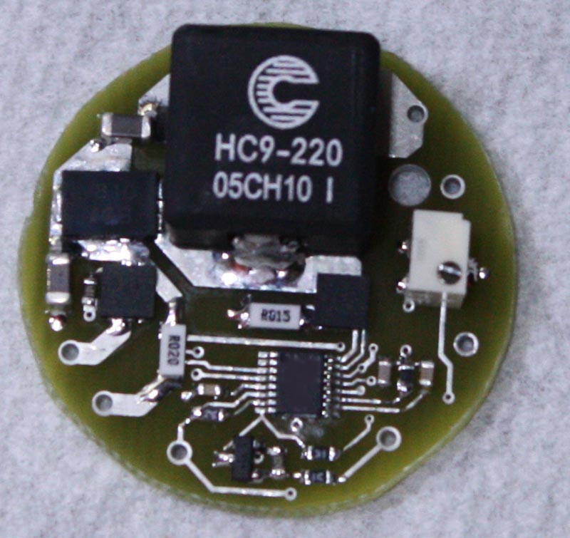
The PCB is 1.2" in diameter, with all components on the top side to ease heatsink mounting requirements. Basically a piece of thermal pad material or thermal adhesive tape will allow it to mount down to a heatsink.

The precision multiturn trimpot is the same one used on the hyperboost/hyperbuck drivers and allows setting of the output current. There is a buffered PWM control input (high going signal will turn off the output). There's also 2 inputs that allow wiring to an external Pot (in parallel with the onboard trimpot) for continuous output current adjustment.

This driver could be directly connected and controlled by a d2Flex driver.

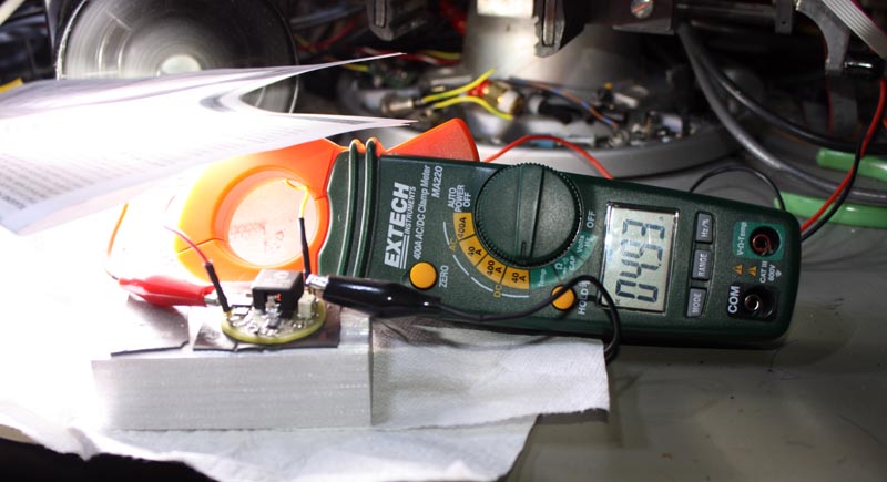
The following picture shows the prototype driver.

h5ccp1.jpg


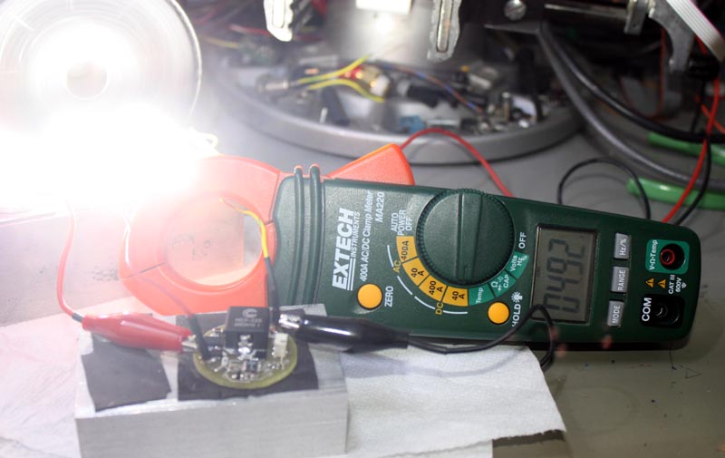
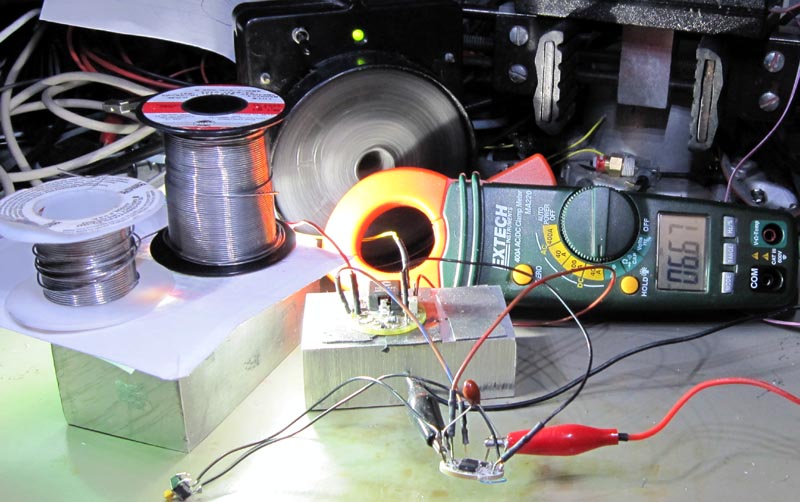
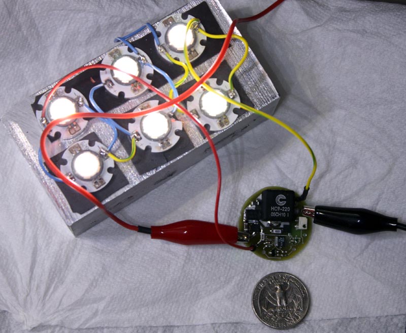
The following shows the driver connected to 6 P7's in (3s2p) to mimic 3 x SST50's in series.

h5ccp2.jpg


The output current is adjusted to a very low level to allow capture of the picture. A US quarter for size comparison.

More testing to do before I run production boards.

cheers,
george.
 

georges80

Flashlight Enthusiast
Joined
Oct 23, 2002
Messages
1,262
Location
Sunnyvale, CA
Re: H5CC driver

Setup running at full output (trimpot set for max current). Nominally 5A output and I ran it for 1 hour 20 minutes.

The driver reached 58C at the hottest component (input FET) with the heatsink reaching 37C at the end of the test. The prototype PCB doesn't have thermal vias for the FETs or Inductor to the bottom surface of the board - I rushed the proto out with another batch of boards I was getting prototyped. I'm actually very please that even without a good thermal path for the 'hot' components on the PCB, that they only reached around 20C higher than the heatsink.

On the production boards I've already changed the layout to incorporate the thermal vias. Basically this board is not stressing at all to push out 45W+ to the 6 P7's.

Here's some pics of it running full output:

h5ccp3.jpg


and with the 'shade' removed from the P7's :)

h5ccp4.jpg


cheers,
george.
 

Fulgeo

Enlightened
Joined
Jan 7, 2008
Messages
467
Location
Michigan USA
Re: H5CC driver

I would also like one or two. Great job. :thumbsup: Let me quote your typical three year old and say "Gimmie Gimmie!"
 

Al Combs

Enlightened
Joined
Jul 2, 2007
Messages
872
Re: H5CC driver

Will this board have a PWM port like the hipCC for the addition of a D2Flex? Will the production version have a pot that can be removed in preference to an external one? Thanks for making it fit in the Mag-D.:twothumbs

Dare I ask is there a H9CC or a H9Flex in the works? :naughty:
 

georges80

Flashlight Enthusiast
Joined
Oct 23, 2002
Messages
1,262
Location
Sunnyvale, CA
Re: H5CC driver

Will this board have a PWM port like the hipCC for the addition of a D2Flex? Will the production version have a pot that can be removed in preference to an external one? Thanks for making it fit in the Mag-D.:twothumbs

Dare I ask is there a H9CC or a H9Flex in the works? :naughty:

Post #24 describes PWM...

Why remove the trimpot - all my drivers (with Pot inputs) are designed to retain the onboard trimpot to be used to trim up an external Pot. Given most pots are +/- 20% I use the onboard trimpot (that ends up in parallel with the external Pot) to adjust the external pot range. Removing on board trimpots would mean you have as bad as +/- 20% current control.

No 9A drivers in the works - that would require too many thermal/battery/contact issues that I don't want to have to deal with AND the inevitable questions from users.

Consider that power losses in any resistive elements goes up by the square of the current, i.e. I x I x R. So, 0.02 ohms in line with the current path for a 5A driver would be 5 x 5 x 0.02 = 0.5W, with 9A that would become 9 x 9 x 0.02 = 1.6W.

I already have a prototype of the H5Flex - I haven't had time to assemble and test it, but given it's the blending of the H5CC and my proven Flex uController/hardware module I'm extremely confident it will work well. The H5Flex is 1.3" in diameter, so still Mag D friendly and with components only on the top surface.

Given the component ratings and how well the thermal operation of this driver is performing it may likely become a H6CC and H6Flex in production...

cheers,
george.
 

georges80

Flashlight Enthusiast
Joined
Oct 23, 2002
Messages
1,262
Location
Sunnyvale, CA
Re: H5CC driver

Ok, I've tested the h5cc with a d2flex and made some minor changes to the firmware (new menu entry) to support the lower dimming capability of the h5cc design versus hipcc.

Output current on low is around 20mA (average of 5A/256) - I can see the individual die of the P7 LEDs, press to high and it goes up to 5A - you don't want to be looking into the LEDs when you do that :)

Click the d2flex/h5cc combo off and standby current consumption drops to <100uA.

The nice thing with the h5cc is you adjust the desired maximum current with the trimpot and then d2flex will PWM dim from low up to the set maximum current. Obviously the h5cc can be run standalone with an external POT or a switch with a few resistor values to click through some fixed output current settings.

cheers,
george.
 

georges80

Flashlight Enthusiast
Joined
Oct 23, 2002
Messages
1,262
Location
Sunnyvale, CA
Re: H6CC driver

I decided to try out the 6A capability before I commit to run production boards. I calculated what the driver should be able to deal with (with safe operating margins) and came up with sense resistor values that will provide 6.67A (nominal) output.

All the components are still within spec - here's the same 6 P7's (2 parallel strings of 3 series LEDs) running at full output. The power to run the H6CC is being provided through the d2flex so I can test the dimming capability. For this picture the output is set on 'high'.

The solder spools are being used to hold down a sheet of paper (that singed...) to keep pressure on the P7's so they don't lift off the thermal pad during the test.

After 10 minutes the aluminium heatsink that the P7's are on was at 62C :)

I measured 10V going to the LEDs and the current was nominal 6.7A - that's 67W hitting those poor LEDs.

I had just over 16V feeding into the H6CC (to keep input current to the driver under 5A - the limit of my power supply). Calculated efficiency is just over 93% for this test case - pretty decent!

The hottest area of the driver reached 62C (input polarity FET) and the heatsink was at 32C (again after 10 minutes). The production board will run cooler, since all the 'hot' components will have thermal paths in place to the bottom of the PCB - the proto only has thermal vias under the switcher controller IC. The inductor, switcher controller, switcher power FET and sense resistors were under 50C.

h6cc1.jpg


cheers,
george.
 

greencardigan

Newly Enlightened
Joined
Jan 16, 2007
Messages
77
Re: H6CC driver

I decided to try out the 6A capability before I commit to run production boards. I calculated what the driver should be able to deal with (with safe operating margins) and came up with sense resistor values that will provide 6.67A (nominal) output.

Can you squeeze another 35% current out of it? :poke:

Actually, 6.67A is probably a good compromise for a SST-90.
 

georges80

Flashlight Enthusiast
Joined
Oct 23, 2002
Messages
1,262
Location
Sunnyvale, CA
Re: H6CC driver

Can you squeeze another 35% current out of it? :poke:

Actually, 6.67A is probably a good compromise for a SST-90.

9A => 9 x 9 = 81
6.67A => 6.67 x 6.67 = 45

So, you can see that your mere 35% 'squeeze' leads to close to 100% higher I^2 resistive power losses...

Higher current output would require a larger inductor (or run it much hotter) or increase in switching frequency for lower inductance, but then higher switching losses. It would need thicker traces, higher dissipation in the sense resistors etc etc.

Anyhow, I aimed for a 5A driver, but decided that given the component specs I could run it up at 6.67A. The multiturn trimpot will allow setting the drive current lower if needed so that will cover SST50 requirements and conservative sst90 implementations. Of course you could run multiple LEDs if needed - my test case above is essentially 3 series SST50's worth of load.

By aiming for a more conservative 6.67A output, the board fits nicely in its 1.2" diameter envelope, has a high quality multiturn trimpot for user current adjustment and also has all components on a single side, simplifying the attachment via thermal pad or thermal adhesive material to a heatsink.

cheers,
george.
 

cocoro1967

Newly Enlightened
Joined
Jan 10, 2010
Messages
5
Location
japan saitama
Re: H6CC driver

:wave:
This item is on sale in time or what?
Very interested.

I own light, SST-90 to 6A I want to drive.
A diameter of 20mm is ideal.
 
Last edited:

netprince

Enlightened
Joined
Sep 7, 2008
Messages
547
Re: H5CC driver

Output current on low is around 20mA (average of 5A/256) - I can see the individual die of the P7 LEDs, press to high and it goes up to 5A - you don't want to be looking into the LEDs when you do that :)

I'm looking forward to having such a large output range, 20ma on low is impressive.
 

videoman

Enlightened
Joined
Jul 26, 2009
Messages
422
Re: H5CC driver

What is the minimum and maximum input voltage range and how much volts does it have to be above led vin to stay in regulation ? Also what temp will thermal shutdown occur? Will it be fine to drive from 7.2v source to power 24 xpg's in 12 strings of series ( alll strings paralleled) ?
 
Top