H6CC 6.7A LED driver

georges80

Flashlight Enthusiast
Joined
Oct 23, 2002
Messages
1,262
Location
Sunnyvale, CA
Re: H6CC driver

Thanks for posting up the links Will.

Given that this driver only has components on the top side, it should be pretty easy to provide a large/wide thermal path versus drivers with components on both sides...

AND..... I have drivers ready to ship - this first batch has a 20V max input voltage, but I doubt that will affect too many folk.

The next run (after this first 20 or so) will have the full 24V input rating.

I will be posting up tech data on my website over the weekend as I perform more tests and take pictures etc. Tech info and pricing can be found via the URL in my sigline.

I have characterized the trimpot resistance versus output current information and that will be going into the tech section so folk can adjust the trimpot for their desired output current.

I will ship the drivers with the trimpot initially set for nominal 2.8A (P7 or 4p MC-E) current output.

cheers,
george.
 

flashfiend

Enlightened
Joined
Dec 28, 2009
Messages
736
Location
Bay Area, CA
Re: H5CC driver

Thanks for the links Will. George, I think this driver is going to be a real winner and its max current may be a sweet spot for many lights.
 

wquiles

Flashaholic
Joined
Jan 10, 2005
Messages
8,459
Location
Texas, USA, Earth
Re: H6CC driver

Thanks for posting up the links Will.

Given that this driver only has components on the top side, it should be pretty easy to provide a large/wide thermal path versus drivers with components on both sides...

AND..... I have drivers ready to ship - this first batch has a 20V max input voltage, but I doubt that will affect too many folk.

The next run (after this first 20 or so) will have the full 24V input rating.

I will be posting up tech data on my website over the weekend as I perform more tests and take pictures etc. Tech info and pricing can be found via the URL in my sigline.

I have characterized the trimpot resistance versus output current information and that will be going into the tech section so folk can adjust the trimpot for their desired output current.

I will ship the drivers with the trimpot initially set for nominal 2.8A (P7 or 4p MC-E) current output.

cheers,
george.

You are welcome George - Payment sent for my first of many of these new drivers ;)
 
Last edited:

Th232

Flashlight Enthusiast
Joined
Dec 25, 2008
Messages
1,064
Location
Sydney, Australia
I'm guessing that for a given Vin and load, the Hyperbuck will be more efficient than the H6CC, if it could you say by how much? Also, will the Hyperbuck now be disco'd?
 

georges80

Flashlight Enthusiast
Joined
Oct 23, 2002
Messages
1,262
Location
Sunnyvale, CA
I'm guessing that for a given Vin and load, the Hyperbuck will be more efficient than the H6CC, if it could you say by how much? Also, will the Hyperbuck now be disco'd?

The hyperbuck is a different beast - it can drive up to 50V from up to 80V input and there's no reason to discontinue it.

cheers,
george.
 

ti-force

Flashlight Enthusiast
Joined
Jan 14, 2009
Messages
1,266
Location
Georgia, U.S.
Hey George,

My driver arrived today safe and sound. Talk about fast shipping! WOW!:twothumbs. Thank you very much.

Casey
 

PM01

Newly Enlightened
Joined
Mar 22, 2010
Messages
16
Got mine also!

These are a work of art...the pictures on the website don't do them justice.

Now to start testing!
 

Hill

Enlightened
Joined
Apr 11, 2008
Messages
318
Location
MA
Re: H5CC driver

Thanks George, that clarifies quite a bit. Being new to a lot of this I am still trying to visualize how the driver would attach to a host/heatsink combo such as Der Wichtel's triple LED heatsink for a Mag D host. Will a custom heatsink have to be made for the driver? I looked at your product info for the hipCC on your site and I see the thermal path you describe and now I'm just trying to figure out where I would attach it to in the build.

Will did a very nice job on that BL heatsink. I am not so fortunate to have a lathe, so I mounted the "massive" hipflex driver on its side with a separate hand cut Al heatsink in this triple MCE build. Hipflex is slightly larger I think than the H6CC, so had to carefully shave off two sides and part of the large black component to fit in the D-cell tube.

DSCN4279.jpg
 
Last edited:

georges80

Flashlight Enthusiast
Joined
Oct 23, 2002
Messages
1,262
Location
Sunnyvale, CA
Yes, the h6cc is 1.2" in diameter (versus 1.4" for hipflex), so it will fit in a D mag tube without any issues.

I still have characterization to do of the driver, but for folk that need a reasonable starting point for adjusting the current setting trimpot the following graph should help.

I'm hoping to get some efficiency curves up over the w/end and a more accurate trimpot adjusting curve up on my website.

Once the trimpot is adjusted higher than about 22.5K (the trimpot is nominally 50K) the current will level at 6.7A (the design limit), so you don't need to worry about adjusting it too high...

h6ccrvsi.gif


cheers,
george.
 

georges80

Flashlight Enthusiast
Joined
Oct 23, 2002
Messages
1,262
Location
Sunnyvale, CA
Finally got some time to run some efficiency measurements. 4 multimeters (2 measuring voltage and 2 measuring current). I swept input voltage from a low end (keeping my powersupply from hitting its 5A current limit) up to about 18.5V (max of my power supply).

I ran 1, 2 and 3 LED tests (Vf around 3.5V, 7V and 10.5V total).

I ran a 2.88A test (P7 type LED load) a 5.00A test (SST-50 at spec) and a 6.6A test (over driven SST-50 type LED load).

First graph (efficiency versus input voltage) is for the 2.88A test:

h6eff2.8.gif


Second graph (efficiency versus input voltage) is for 5.0A test:

h6eff5.gif


Third graph (efficiency versus input voltage) is for 6.6A test:

h6eff6.6.gif


As for a typical buck converter, you can see efficiency is higher when input voltage is closer to output voltage. Also, efficiency is higher for 3 LEDs versus 2 LEDs versus 1 LED.

The tests were performed with a production H6CC chosen at random. Note, H6CC drivers include reverse polarity protection (low Rdson FET), so realize that the efficiency numbers reflect the complete input/output performance of a production board, not a hypothetical best case driver with no reverse polarity protection.

cheers,
george.
 
Last edited:

nailbender

Flashlight Enthusiast
Joined
Nov 9, 2008
Messages
3,682
Location
North Carolina
Hi George

I just had to comment on how well this new driver worked. I finished a triple SST 50 built on a DW heat sink and used your new H6CC with a D2flex for dimming and it worked flawlessly. The member that wanted the light will actually use the light so I set the pot at 4.94 amps and all worked perfect.
The D2flex is easy to wire in and I was able to heat sink the driver and get all in a maglite no problem

I just wanted to say thank you for such a great product, works exactly as described with the same great quality as all of your offerings. It was much easier than wiring a bunch of drivers together to achieve the desired amperage.


Thanks again George for another great product.

Dave
 

tva

Newly Enlightened
Joined
May 7, 2010
Messages
1
Hi George,

I am modding a dive torch to use a P90 led. Since the batteries and switches are going to be reused, I am stuck with the 12V the batteries provide.

I already tried a set of linear drivers in parallel, but they get too hot seen the big step-down in voltage. Let alone the efficiency which will be below any usable level.

Also looked at this chip : http://www.linear.com/pc/productDetail.jsp?navId=H0,C1,C1768,P89897 , which will support 20A within workable voltage limits.

It is actually looking very promising, but I doubt if I can build the whole setup, all components included, small enough to fit into the dive torch...

Therefor I would be very interested to work with the H6CC driver this thread is about. At 6A the P90 is not at his max. but probably more than enough for use.

Could you give me some instructions around price and where to order ?
(I presume here you are still selling ready2use items...)

Thanks in advance,

T.
 

ti-force

Flashlight Enthusiast
Joined
Jan 14, 2009
Messages
1,266
Location
Georgia, U.S.
Hi George,

I am modding a dive torch to use a P90 led. Since the batteries and switches are going to be reused, I am stuck with the 12V the batteries provide.

I already tried a set of linear drivers in parallel, but they get too hot seen the big step-down in voltage. Let alone the efficiency which will be below any usable level.

Also looked at this chip : http://www.linear.com/pc/productDetail.jsp?navId=H0,C1,C1768,P89897 , which will support 20A within workable voltage limits.

It is actually looking very promising, but I doubt if I can build the whole setup, all components included, small enough to fit into the dive torch...

Therefor I would be very interested to work with the H6CC driver this thread is about. At 6A the P90 is not at his max. but probably more than enough for use.

Could you give me some instructions around price and where to order ?
(I presume here you are still selling ready2use items...)

Thanks in advance,

T.
Click below:
H6CC Driver
 

clint357

Newly Enlightened
Joined
Mar 31, 2009
Messages
184
Location
Grand Rapids, MI
The web page shows that you can pot these things as long as the potting compound is not conductive. I just wanted to make sure that these will not get too hot. Thermal potting compounds DO conduct heat, but not that well. Have you tried potting these yet? I just don't want to buy one and have it overheat. Thanks.
 

georges80

Flashlight Enthusiast
Joined
Oct 23, 2002
Messages
1,262
Location
Sunnyvale, CA
The web page shows that you can pot these things as long as the potting compound is not conductive. I just wanted to make sure that these will not get too hot. Thermal potting compounds DO conduct heat, but not that well. Have you tried potting these yet? I just don't want to buy one and have it overheat. Thanks.

My general comments on potting and heatsinking of ANY of these new high current drivers (we're talking >2A here). I'm just choosing your email question to start off my discussion below:


The potting reference in the H6CC tech section is to the top of the board - for water proofing etc. I'll have to clarify that on my website.

It is the user's responsibility to calculate the heat dissipation in the driver - since you now have some efficiency curves to base your calculation on. You need to determine the watts be dissipated in your system and determine if the level of heat being generated in the driver and LED can be handled.

Just potting it into a brick and letting sit in a housing will obviously not be able to dissipate enough heat. That would be no better than using thermal epoxy to mount the driver to a small heatsink. e.g. if the driver is dissipating 2W, then whatever it is mounted on has to be able to dissipate that 2W AND maintain a stable temperature.

As you can imagine, I can't recommend whether potting would work or not - way too many variables including what kind of potting material, what shape you make the 'brick' (distance from the surface of the potting edge to the various devices on the H6CC board) and then how is the 'brick' mounted to the body of the light. What current you've set the output to? How many LEDs? What battery source? etc etc....

In summary, I HIGHLY recommend that you use the thermal pad (which I supply) or thermal adhesive tape to attach the bottom of the H6CC driver to your heatsink. That's the specific reason the H6CC was designed with components only on the top surface. This same scheme was used with the hipcc/hipflex/hyperboost and hyperbuck drivers (all high power drivers) very successfully.

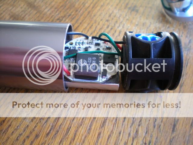
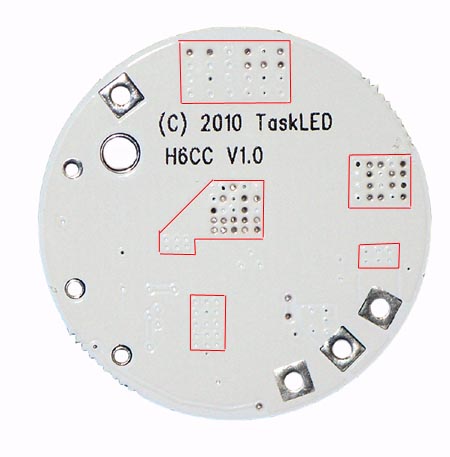
Designing a high power driver that does not deal with how to cool the devices is only providing 1/2 the solution to the customer. All the high power drivers I've designed since the maxflex have had to address the thermal path. Most of the new high power IC's, FETs etc utilize the PCB to remove heat - the switcher controller on the H6CC has a thermal pad UNDER the IC (same as per maxflex) that you can't see after the part has been soldered down to the PCB. Same with the FETs on H6CC. There are multiple vias under the switcher IC and FETs (and inductor and power resistors) to transfer heat from these devices to the bottom side of the PCB. You can see some of those thermal areas in this picture:

h6ccbot.jpg


and it is those thermal areas that need the thermal pad to heatsink interface to transfer the heat from the devices.

With folk wanting drivers that can handle 30W to close to 100W you will have many watts being dissipated in the drivers - the cooling of the drivers is as important as the cooling effort being placed on the LED heatsink design.

Simple calculation here of a rather 'stressful' light). Assume you have 6.7A going to your 3 x SST-50/90's. That means 6.7 x 3.5 x 3 = 70W going to the LEDs. Assume you're powering this from 14.4V. From the efficiency curves in this thread, you have around 92% efficiency in the driver which is pretty decent. You will still have 70W x 8% = 5.6W being dissipated in the driver that needs to be removed from the driver. Potting the driver is not going to work.

Anyhow, in summary... I know a lot of folk (just read some of the somewhat recent SST50/90 threads) are all excited to get a driver for these new LEDs so they can build the meanest light out there... Great, but it's not quite the same as taking an XP-G and a 3W driver and making a pill for an xyz donor body. Even a single SST-50 driven at 5A is around 20W of system 'heat' that needs to be managed efficiently or you've just tossed a bunch of $$$ into the fire pit. That management requires attention to the LED heatsink AND attention to how the driver is going to be mounted to a heatsink AND the thermal paths from the heatsink to the body of the light.

Take care of the heat dissipation issues and the lights we build will work great and for more than a couple of minutes...

cheers,
george.
 
Top